Download PDF
Download page Thermo-6 test instructions.
Thermo-6 test instructions
Video guide
Follow the QR code link to watch the YouTube video.

Test principle
NOTE!
The quality test in the factory and at the customer's site with the test device refer to different reference measurement variables. If a quality test is carried out with the test device on a newly delivered temperature control unit, the measurement accuracy of the measured variables may differ from one another.
NOTE!
Value inputs from the Pt 100 temperature measurement into ohms (Ω) are converted into degrees Celsius (°C) using a formula. The basis is the Pt 100 table in accordance with ITS-90 (International Temperature Scale).
Preparation
NOTE!
To make optimum use of the cooling capacity of the temperature control unit, keep the cooling water outlet as short as possible and free of back pressure.
- Remove any existing Main line and return connections.
→ Any pre-installed intermediate adapter, which was used with units up to 2226-nnn, must be left on the unit. - Connect the HB-TP180 test device to the Thermo-6 unit.
- Connect the cooling water inlet and outlet to the cooling water network.
- Optional connect the system water inlet and outlet to the system water network.
- Connect to the electrical grid.
- Provide Pt 100 reference measurement equipment.
Settings

By default, 2 predefined test temperatures are applied (40 °C and maximum temperature). In addition, 2 additional test temperatures are available if required.
- On the home basic screen, tap the main menu button ().

- Select [Quality Test] > [Test Temperature 3] or [Test Temperature 4].
- Set the parameter to the desired value.
- Switch on the function with the slider (
 ).
).
NOTE!
The predefined test temperatures of the test procedure (40 °C and maximum temperature) cannot be changed. The maximum temperature that is reached during the test process depends on the type of unit (maximum main line temperature).
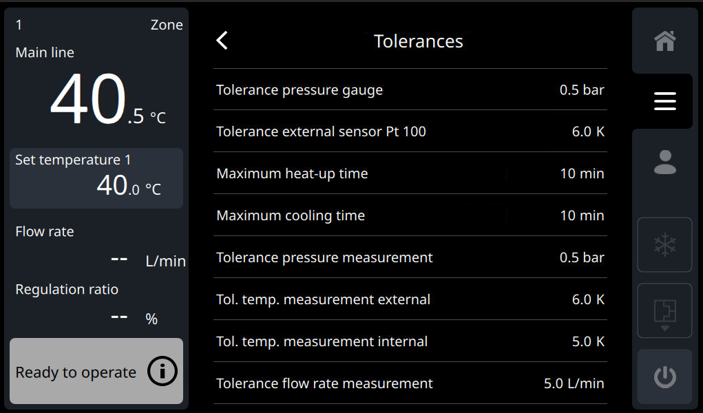
The tolerances determine which deviations between the components are permitted in order to pass the quality test.
- On the home basic screen, tap the main menu button ().
- Select [Quality Test] > [Tolerances] > [...].
- Set the parameter to the desired value.
NOTE!
The tolerances are set as standard in accordance with the recommendation of HB-Therm.
At the end of the quality test, the measurement values listed below can be compared by the Thermo-6 with the reference measurement values entered.
- Temperatures (Main line and Return line)
- Pressure (system pressure, main line pressure and return pressure (if ZF is available))
- Flow rate (Flow rate measurement)
If the optional adjustment is not carried out at the end of the quality test, this can be done at a later date. A new test run is not necessary. The prerequisite is that the approval has already been carried out once.
- On the home basic screen, tap the main menu button ().
- Select [Quality Test] > [Accept Calibrating]
- Tap the play symbol (
 ) to start the process.
Quality test
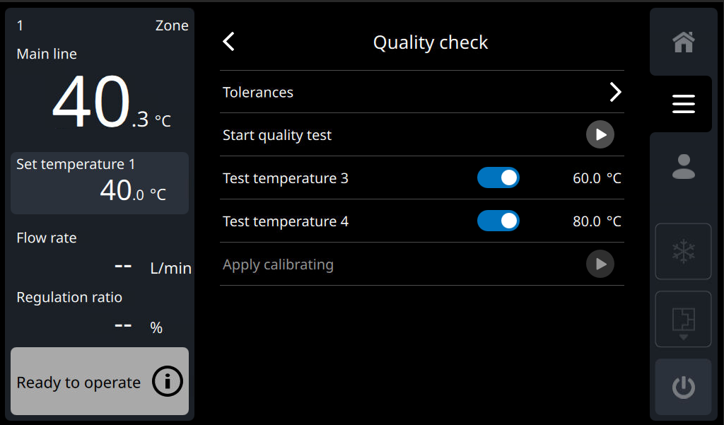
- On the home basic screen, tap the main menu button ().
- Select [Quality Test] > [Start Quality Test].
- Tap the play symbol () to start the process. The quality test can only be started in the “ready to operate” status (unit is switched off).
→ The quality test starts automatically.
→ Follow the on-screen instructions.
NOTE!
At the end of the quality test, a CSV file can be saved on a USB data carrier to create a test and calibration certificate (the CSV file can also be saved on a USB data carrier later via the [Save/Load] > [Export Quality Test ] Menu ). With the VIP software (visualisation program → download ), a test and calibration certificate can be created. See also section 'Test protocol'.
NOTE!
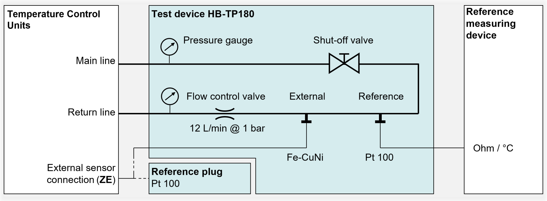
When measuring the Pt 100 reference temperature with the multimeter, the ohmic resistor of the test lines must be taken into account. This resistor must be subtracted from the measurement result. The ohmic resistor of the measurement lines supplied by HB-Therm is 0.3 ohms, which corresponds to a measurement error of approx. 0.8 K.
HB-TP180 shut-off valve position!
![]()
Connect the HB-TP180 with serial number ≥1817-nnn to the Thermo-6 unit and bring the shut-off valve to the “open” position. | |
| Description | User interaction |
|---|---|
| START QUALITY TEST | |
unit = ON (The unit starts filling and venting the system circuit) |
|
1/9: MAXIMUM PRESSURE | |
Set temperature = 40 °C
|
|
2/9: EXTERNAL SENSOR | |
Set temperature = 40 °C
|
|
3/9: MAXIMUM PUMP PRESSURE | |
Set temperature = 40 °C
|
|
4/9: MAXIMUM TEMPERATURE | |
Set temperature = maximum device temperature
|
|
5/9: TEMPERATURE 40 °C | |
Set temperature = 40 °C
|
|
6/9: FLOW RATE ZERO | |
Set temperature = 40 °C
|
|
7/9: ADDITIONAL TEST TEMPERATURE (OPTIONAL) | |
Set temperature = according to parameter [Test temperature 3] and [Test temperature 4]
|
|
8/9: PRESSURE AT 0 BAR | |
Unit = OFF (The unit is cooled, emptied and depressurised)
|
|
9/9: CONCLUSION | |
Unit = OFF
|
|
Safety check
For the safety check, remove the unit cover and reassemble it correctly after completion (→ Open unit).
ATTENTION!
Working with the unit requires knowledge of the safety instructions and quick guide. That's why:
Read the safety instructions and quick guide carefully before starting any work. The basic requirement for safe work is compliance with all safety instructions and careful action by qualified qualified personnel to prevent accidents involving personal injury and property damage.
The following optical tests must be carried out:
| Approval | Description |
|---|---|
| Mains cable | Check isolation and connection area for damage. |
| Thermal isolation | Check insulation for damage and placement. |
| Tightness | Check the unit (connections) for leaks. |
| General condition | Check the unit for damage and fouling. |
Test report
After the quality test is complete, the protocol can be saved on a USB data carrier. If you want to save the protocol to a USB data carrier at a later date, proceed as follows:
NOTE!
USB data carriers formatted with FAT, FAT32, exFAT and ext2/3/4 are supported.
- Connect the USB data carrier to the front connector.
- On the basic screen, tap the main menu button
- Select [Save/Load] > [Export Quality Test].
- Tap the disk symbol
 to start the process.
→ The data is written to the USB data carrier as a CSV file (e.g. “Qual_ _ _<hhmmss.csv <UnitBasicType><YYYYMMDD>”). The information system is opened automatically and the current progress is displayed.
NOTE!
With the VIP software (visualisation program → download), a test and calibration certificate can be created.