Download PDF
Download page Remote control.
Remote control
In order to control system the Thermo-6 temperature control unit via an external controller, the following Interfaces are available for the connection between the unit and the machine.
NOTE!
When remote control is activated, all protocol-related settings and functions are blocked on the local command.
The remote control address is used for unique identification for all data Interfaces and may only be assigned once in the communication network. If a Gate-6 act present in the communication network, it recognizes duplicate remote control addresses and reports them.
Interface Ethernet (OPC UA)
Data is exchanged either directly between the machine control and the Thermo-6 temperature control unit or via the Interface Server Gate-6. For further Information about the interface, click here...

Close the control cables as shown in the image.
On the home basic screen, tap the menu button

Select [Setting] > [Remote Control] > [Remote Control Address]
Set the parameter to the desired value
Only with Gate-6 in a communication network
On the home basic screen, tap the menu button
Select [Gate] > [Setting] > [Network Gate-6] > [Network Configuration Gate-6]
Set parameter as described in the following table, see here...

If access to Gate-6 is not possible (LED on Gate-6 blinks green), check the jumper cable and network configuration on the Thermo-6. Network setting must be set to “automatically.” If the setting is correct and a connection is still no established, reset the network setting on Gate-6. To do this, hold down the reset button on the Gate-6 for 3 seconds.
Select [Setting] > [Remote Control] > [Network] > [Network Configuration]
Set the parameter to the desired value, as explained in the table below, click here...
Select [Functions] > [Remote Control]
Switch on the function with the slider. When remote control is activated, the remote control symbol is displayed on the basic screen
 .
.
Network configuration
The DHCP server (DHCP = Dynamic Host Configuration Protocol) automatically assigns IP addresses on the network. By default, HB-Therm units are configured to automatically obtain IP addresses (default setting).
Setting (Thermo-6/Gate-6) | Description |
“automatically” [Network configuration ] or [Network Configuration Gate-6] Parameter | DHCP server available If a DHCP server act available, connected units automatically receive a network address (IP address that does not start with 169.254...). The temperature control units are assigned to the machine control system (see injection moulding machine instructions). |
Not clear whether a DHCP server is available Leave the network configuration as default (automatically) for now. If the network address (IP address that does not start with 169.254...) is assignment automatically, a DHCP server is available. If no DHCP server act available, the unit itself assigns an IP address that starts with 169.254... In this case, communication with the machine control is no possible. The IP address setting (current) can be read on the temperature control unit under [Setting] > [Remote Control] > [Network Configuration] or on Gate-6 under [Gate] > [Setting] > [Network Gate-6 ] > [Network Configuration Gate-6]:
In this case, the network configuration must be carried out manual (see description parameter [Network Configuration] = “manual”, no DHCP server available). | |
“manual” Parameters [Network configuration] or [Network Configuration Gate-6] | no DHCP server available If no DHCP server act available, a unique IP address must be manual assigned to each Thermo-6 and Gate-6. The permitted IP address range depends on the machine control or the manufacturer and must be clarified with them. For communication between the machine control, Gate-6 and Thermo-6 to work, all participants must be in the same network. The IP address ranges from the following manufacturers are known:
|
Help with problems
Problem | Remediation |
|---|---|
The Thermo-6 temperature control unit is not recognized in the existing device network. → Gate-6 symbol does not | Check whether the network configurations are set differently between the temperature control unit and the units in the device network.
|
The interface server Gate-6 is not recognized in the device network (e.g. When the Gate-6 is replaced). → Gate-6 symbol does not → Gate-6 LED status luminaire flashes green | The following two scenarios can occur, caused by different network configuration settings (automatic/manual): Scenario 1: Existing network is configured to “automatically” (DHCP server available) Problem
solution
The network configuration of Gate-6 is thus reset to the default setting (automatically). |
Scenario 2: Existing network is configured to “manual” (no DHCP server available) Problem
solution
| |
Communication is available, but the unit does no accept commands from the machine control. | Check whether the remote control symbol appears on If not
|
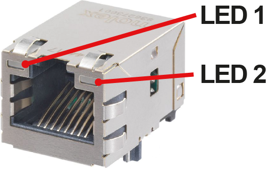
Act the Ethernet cable okay?
| Check whether the LEDs on the Thermo-6 or Gate-6 Ethernet connector behave as follows.
|
Communication is not working | Verify that the port address is correctly set on the injection moulding machine. Port 4841 is defined and reserved for temperature control units Thermo-6. |
Check whether the Internet Protocol version is correct. Temperature control units Thermo-6 only support IPv4. | |
Check whether the EUROMAP 82.1 version is compatible. There are two OPC UA standards that are not compatible. The client (injection moulding machine) must support both standards. The server (temperature control unit) determines which standard is used for communication. The HB-Therm units have implemented the following EUROMAP 82.1 standards
Which version is supported by machine manufacturers depends on the software-version of the machine control system and must be clarified with the machine manufacturer. The software versions of the following machine manufacturers are known: Engel
|
Interface DIGITAL (ZD, ZC)
Data is exchanged between the machine control and the Thermo-6 temperature control unit via the Interface Server Gate-6. For further Information about the interface, click here...
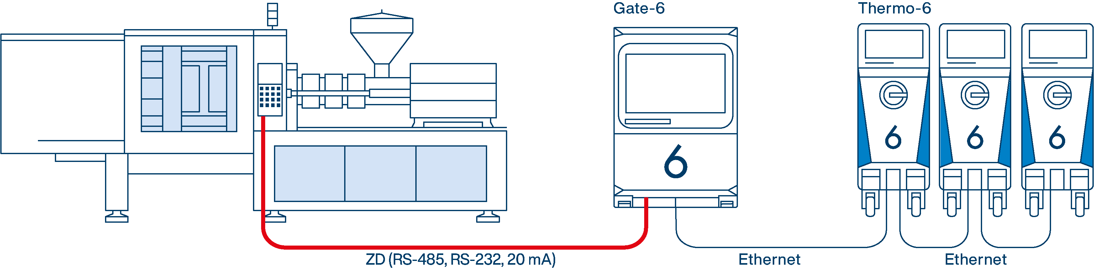
Connect the control cable as shown in the image
On the home basic screen, tap the menu button
Select [Setting] > [Remote Control] > [Remote Control Address]
Set the parameter to the desired value
Select [Gate] > [Protocol Converter] > [Protocol]
Set the parameter to the desired value
Select [Functions] > [Remote Control]
Switch on the function with the slider. When remote control is activated, the remote control symbol is displayed on the basic screen
Protocol | Machine manufacturer / system |
|---|---|
OFF | Protocol converter disabled data transfer via the Interface Server Gate-6 via the OPC UA Ethernet interface. |
1 | Arburg, Billion, Bühler, Dr. Boy, Ferromatik Milacron, KraussMaffei, Negri Bossi, Sumitomo Demag, Wittmann Battenfeld, Zhafir |
2 | CAN-Bus (Sumitomo Demag) |
4 | Engel, Haitian |
5 | Stork |
9 | CANopen (Euromap 66; Netstal, ...) |
15 | PROFIBUS-DP |
16 | SPI (Fanuc, ...) |
Help with problems
Problem | Remediation |
|---|---|
The Thermo-6 temperature control unit is not recognized in an existing network of devices. → Gate-6 symbol does not | Check whether the network configurations are set differently between the temperature control unit and the units in the device network.
|
The interface server Gate-6 is not recognized in the device network (e.g. When the Gate-6 is replaced). → Gate-6 symbol does not → Gate-6 LED status luminaire flashes green → The [Gate] menu does not display any submenus such as [Protocol Converter ] | Check whether the network configuration for Thermo-6 and Gate-6 is set to “automatically.”
Wait approx. 30 seconds. If the LED on the Gate-6 continues to blink green afterwards, reset the network setting on the Gate-6:
|
External control (ZB)
Communication between the machine control and the Thermo-6 temperature control unit takes place via potential-free external contacts. For further Information about the interface, click here...
Connect the control cable to the front of the unit.
NOTE!
The [Remote Control] function does not have to be switched on for external control.