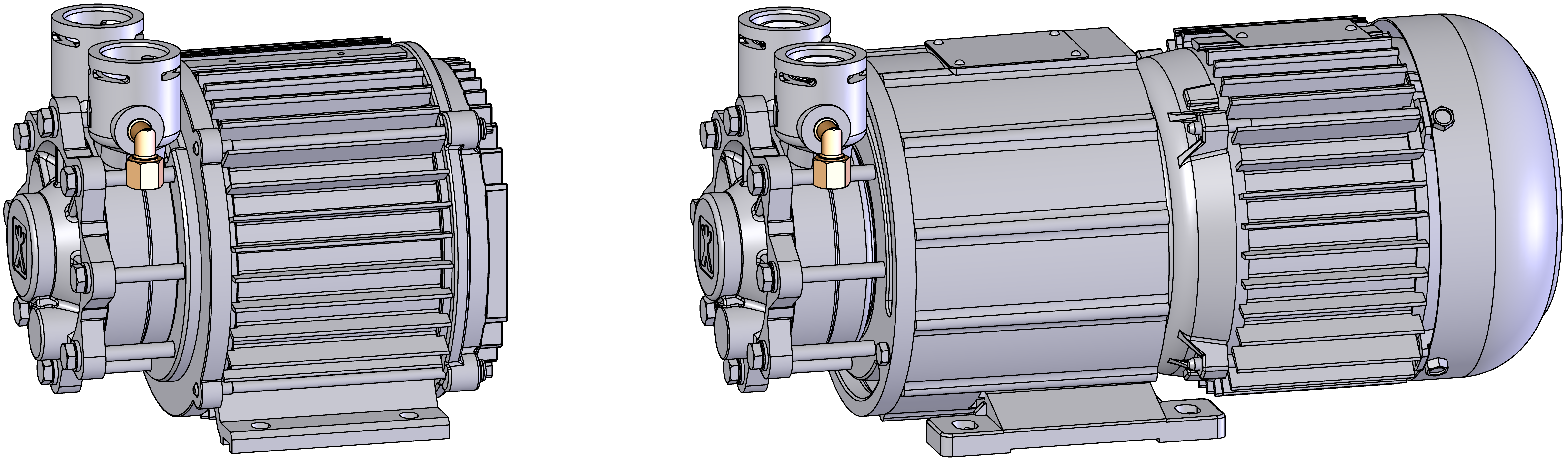
T28582, T28583, T28640, T28639 replacement pump with motor
Qualification
Qualified personnel
Material
Pos | Designation | Article | Number |
|---|---|---|---|
| 01 | Pump 4T, AY-4271-PM-SR.0005, 380–480 V | T28582 | 1 |
| 01 | Pump 4T, AY-4271-PM-SR.0006, 200–240 | T28583 | 1 |
| 01 | Pump 4S, AY-4271-PM.0001, 380–480 V | T28640 | 1 |
| 01 | Pump 4S, AY-4271-PM.0002, 200–240 V | T28639 | 1 |
| 02 | O-ring FPM75 20x3 (optional for piping) | T28656 | 1—4 |
Required material
- Torx screwdriver, size 20, 30
- Open end wrench, size 10, 12
- Assembly grease for O-ring (e.g. Silicone grease)
- Thread sealant (e.g. Loctite 620 liquid seal)
- Cable tie
Procedure
ATTENTION!
Working with the unit requires knowledge of the safety instructions and quick guide. That's why:
Read the safety instructions and quick guide carefully before starting any work. The basic requirement for safe work is compliance with all safety instructions and careful action by qualified qualified personnel to prevent accidents involving personal injury and property damage.
Danger to life due to magnetic field!
The strong magnetic field in the area of the magnetically coupled pump can endanger the lives of people with pacemakers. Therefore:
Make sure that people with a pacemaker do not carry out any maintenance work that would result in dismantling the magnetic coupling (pump head replacement, split cup seal replacement).
NOTE!
In fully assembled pumps, the magnetic fields are completely shielded by the components surrounding them and there is no danger either when the pump is stationary or in operation.
Cool down and empty the unit
-
Switch off the unit using the I/O button (
 ).
).
→ The unit switches off and, if necessary, is cooled and depressurised.
- On the basic screen, tap the function button (
 ).
). - On the basic screen, tap the function button (
 ).
).
→ The unit cools down and evacuation the mold before switching it off.
Check pressure
- Select [Display] > [Actual Values] > [System Pressure].
→ The system pressure must display 0.0 (±0.1) bar. - The pressure shown by the pressure gauge must be 0.0 (+0.3) bar.
- Switch off the main switch (QS 1), pull out the mains-connector.
Remove covers and open the front
- Remove covers from the unit (→ Open unit).
- Open the front door and fold the front completely down by loosening the two Torx screws.
- Remove the protective cover in the electrical housing by removing the Torx screws.
Replace pump with motor
ATTENTION!
Screw connections are sealed with thread sealant and are therefore slow to release. Otherwise, there is a danger that the screw connection will be damaged (e.g. Tearing off the screw head). That's why:
- If possible, warm up the adhesive compound beforehand
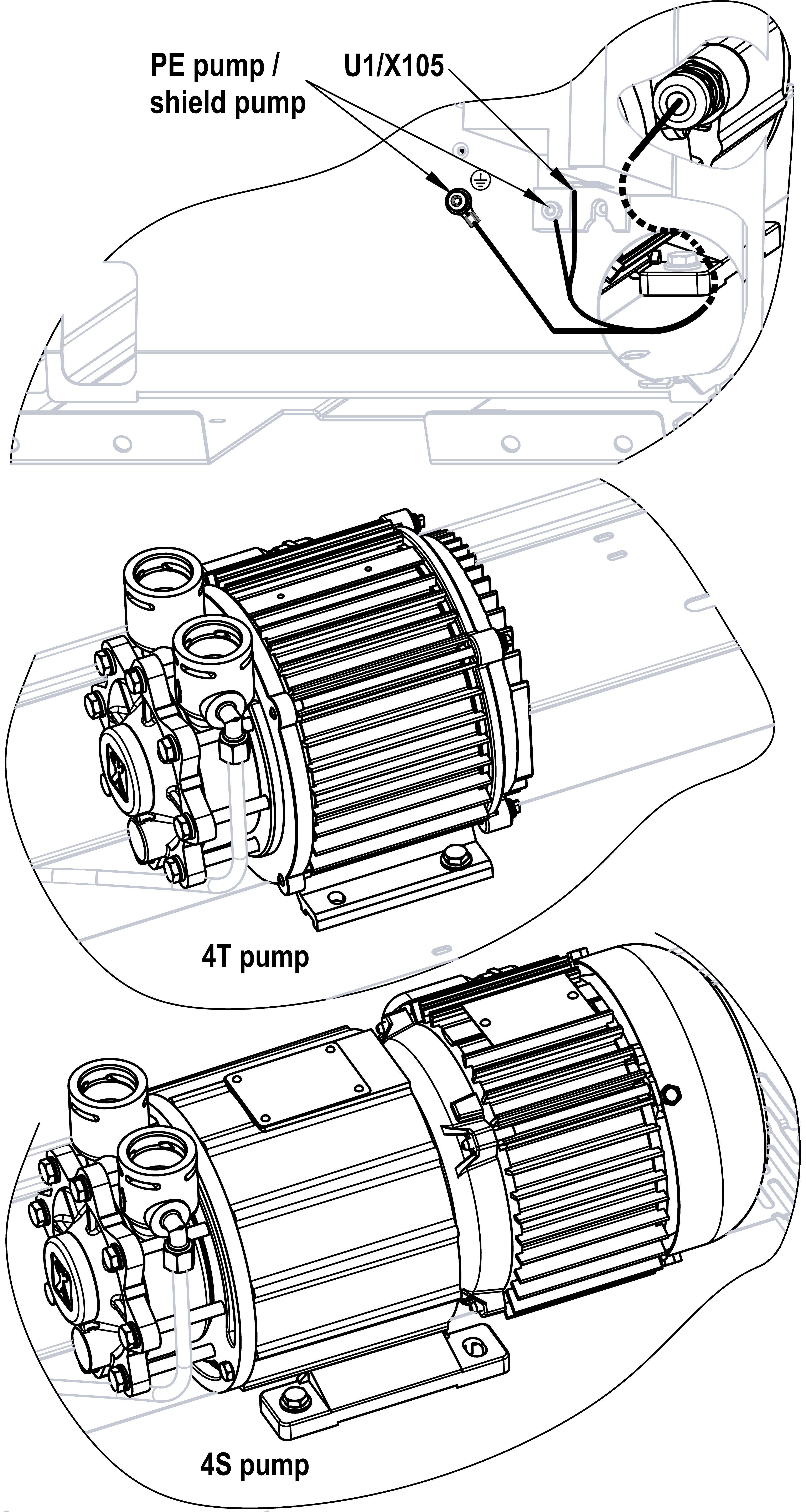
- Unplug the X105 connector from the frequency converter (U 1) and remove the grounding wires from the electrical housing.
- Unscrew the screws securing the pumps, remove the screws.
- Remove pipes leading to pumping. To do this, remove the mounting clips.
- Depending on the type of unit, the pipe must be moved/released axially to the respective connection in order to remove it.
- Remove the flexible tube from the angle fitting (pump pressure connection), if available.
- Remove the pump from the unit.
- Remove the angle fitting from the pump pressure connection.
- Install the angle fitting on the new pump with thread sealant.
- Insert a new pump into the unit and loosely install the mounting screws (do not tighten yet).
- Check pipe O-rings for wear and replace if necessary.
- As an assembly aid, it is recommended to use mounting grease for the O-rings.
- Install pipes and install mounting clips.
- Tighten the pump mounting bolts.
- Install the flexible tube to the angle fitting (pump pressure connection) and tighten.
- Re-plug connection X105 on the frequency converter (U 1) and secure the grounding wires to the electrical housing.
Close front
- Install the protective cover around the electrical housing and secure with Torx screws.
- Fold up the front and secure 2x Torx screws.
Check tightness and function
- Connect the mains-connector and switch on the main switch (QS 1).
-
Switch on the unit using the I/O button (), check the tightness and function of the unit.
- Optional use the HB-TP checking facility for quality test.
- Reset component maintenance interval. Click here...
Switch off unit and install covers
- On the basic screen, tap the function button (
 ).
).
→ The unit cools down until the temperature is lower than the cooling temperature. The unit then switches off.
-
Switch off the unit using the I/O button ().
→ The unit switches off and, if necessary, is cooled and depressurised. - Switch off the main switch (QS 1).
- Re-attach covers from the unit (→ Open unit).