Download PDF
Download page T28971, T28972: pump impeller and seal.
T28971, T28972: pump impeller and seal
purpose
Pump impeller replacement
qualification
Qualified personnel
Material
| Pos. | Designation | article | number |
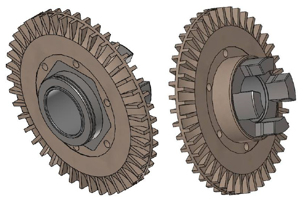
| 01 | pump impeller PEEK 69,6x6,85 | T28971 | 1 |
| 02 | graphite seal 86,5x81x2,2 | T28972 | 1 |
Required material
- Torx screwdriver, size 20, 30
- Open end wrench, size 10, 12
- Ring spanner, size 10
procedure
ATTENTION!
Working with the unit requires knowledge of the safety instructions and quick guide. That's why:
Read the safety instructions and quick guide carefully before starting any work. The basic requirement for safe work is compliance with all safety instructions and careful action by qualified qualified personnel to prevent accidents involving personal injury and property damage.
Danger to life due to magnetic field!
The strong magnetic field in the area of the magnetically coupled pump can be life-threatening for people with pacemakers. Therefore:
— Make sure that people with pacemakers do not carry out any maintenance work that requires the magnetic coupling to be dismantled (pump head replacement, split cup seal replacement).
NOTE!
In fully assembled pumps, the magnetic fields are completely shielded by the surrounding components, so there is no danger either when stationary or during operation.
Cooling / emptying
- On the basic screen, tap the function button (
 ).
). - On the basic screen, tap the function button (
 ).
).- The unit cools down and evacuation the mold before switching it off.
Check pressure / remove covers
- Select [Display] > [Actual Values] > [System Pressure].
- The system pressure must display 0.0 (±0.1) bar.
- The pressure shown by the pressure gauge must be 0.0 (+0.3) bar.
- Switch off the main switch (QS 1), pull out the mains-connector.
- Remove covers from the unit (→ Open unit).
Replace spare part
- Remove the pump and place it on a flat, non-magnetic mounting surface.
- If necessary, follow the additional instructions in the 'Pump' spare parts manual. Click here...
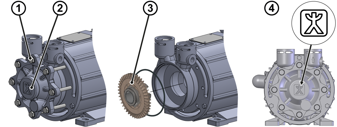
- Release the housing cover with 8x hexagonal screws ①
- Remove screws and housing cover ②
- Remove the pump impeller from the ceramic shaft ③
- If necessary, use a puller. For more information, please contact HB-Therm.
NOTE!
Running and sealing surfaces must be clean and free from contamination. Damaged graphite seals should be replaced if necessary (available as an option).
- Push the new pump impeller onto the ceramic shaft ③
- Check the graphite seal for wear and replace if necessary.
- Place the housing cover and adjust it so that the marking is
 upright and parallel to the mounting surface ④.
 - Install 8x hexagonal screws ① and screw the housing cover ②.
- Reinstall the pump into the unit.
- If necessary, follow the additional instructions in the 'Pump' spare parts manual. Click here...
Check tightness / function
- Connect the mains-connector and switch on the main switch (QS 1).
-
Switch on the unit using the I/O button (
 ), check the tightness and function of the unit.
- Optional use the HB-TP test device for quality test.
- Reset component maintenance interval. Click here...
Switch off / install covers
-
Switch off the unit using the I/O button ().
- The unit switches off and, if necessary, is cooled and depressurised.
- Switch off the main switch (QS 1).
- Re-attach covers from the unit (→ Open unit).