Download PDF
Download page T29197-X, T29344-X: Heating 8+16 kW (4T/4S).
T29197-X, T29344-X: Heating 8+16 kW (4T/4S)

Purpose
Replacing the Heating (EH 1)
Qualification
Qualified personnel
Material
| Pos | Designation | Article | T29197-1 | T29197-2 | T29344-1 | T29344-2 |
| 01 | Heating 8 kW, 3x400/460V | T29156-1 | 1 | - | - | - |
| 02 | Heating 8 kW, 3x220V | T29156-2 | - | 1 | - | - |
| 03 | Heating 16 kW, 3x400/460V | T29008-1 | - | - | 1 | - |
| 04 | Heating 16 kW, 3x220V | T29008-2 | - | - | - | 1 |
| 05 | Screw plug 1/8 – CuZn | T15568 | 1 | 1 | 1 | 1 |
| 06 | Screw connector 6i-1/8 – CuZn | T21203 | 1 | 1 | 1 | 1 |
| 07 | Optional for pipeline: O-ring 20x3 – FPM | T28656 | - | - | - | - |
Required material
- Torx screwdriver, size 20, 30
- open-end wrench, size 10
- thread sealant (e.g. Loctite 620 liquid seal)
- Assembly grease for O-ring (e.g. Silicone grease)
Procedure
ATTENTION!
Working with the unit requires knowledge of the safety instructions and quick guide. That's why:
Read the safety instructions and quick guide carefully before starting any work. The basic requirement for safe work is compliance with all safety instructions and careful action by qualified qualified personnel to prevent accidents involving personal injury and property damage.
Cooling / emptying
- On the basic screen, tap the function button (
 ).
). - On the basic screen, tap the function button (
 ).
).- The unit cools down and evacuation the mold before switching it off.
Check pressure
- Select [Display] > [Actual Values] > [System Pressure].
- The system pressure must display 0.0 (±0.1) bar.
- The pressure shown by the pressure gauge must be 0.0 (+0.3) bar.
Switch off / remove connections
- Switch off the main switch (QS 1), pull out the mains-connector.
- Remove all external hydraulic connections on the Main line (OUT) and Return line (IN).
- For units with a serial number up to 2413-nnn: Remove the intermediate adapter.
Remove covers / open front
- Remove covers from the unit (→ Open unit).
- Open the front door and fold the front completely down by loosening the two Torx screws.
- Remove the entire upper air duct cover. To do this, unscrew and remove 6 mounting screws.
Unplug cable / remove pipes
- Unplug the X302.X and/or X303.X connector from the ZSM-61 power measurement board.
- 400/460 V: X302.X → A 8.1 (ZSM-61)
- 220 V: X302.X, X303.X → A 8.1 (ZSM-61)
- Completely remove the heating cable.
- Remove all piping. Water may escape when the connections are opened. To make it easier to remove the pipes and heating, the following steps must be carried out:
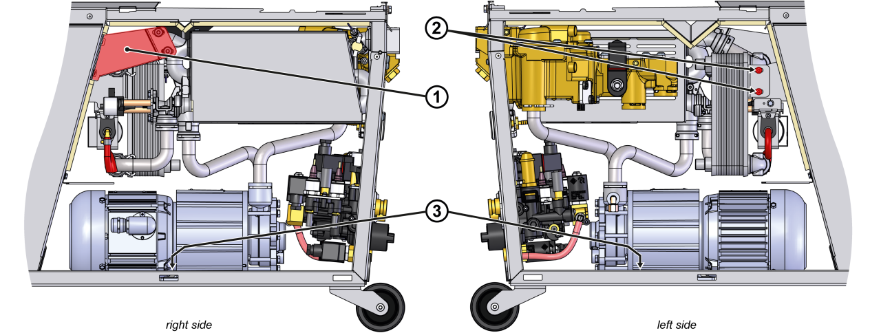
- Remove bracket ①
- Remove the cooler and pump mounting screws ②, ③.
- Remove the mounting clips (split pins) from the pipe connections.
Remove the heat transfer medium module (WTM)
- Remove the heat transfer module mounting screws on the back wall of the unit.
- Extend the heat transfer medium module sideways and set aside.
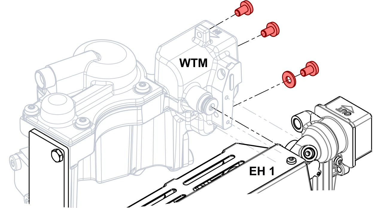
Remove heater module (EH_1)
- Remove the heater module mounting screws on the back wall of the unit.
- Extend the heater module and set it aside.
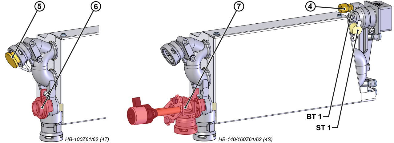
- Remove the temperature sensor (BT_1) and thermostat (ST_1) and transfer them to the new Heating.
- Make sure the thermostat is firmly attached to the surface.
- Install the supplied screw connector to the new Heating with thread sealant ④
- without additional equipment_ZG: T15568
- with additional equipment_ZG: T21203
- Unneeded screw connector can be discarded.
- Transfer device-specific components.
- HB-100Z61/62: Remove the sealing plug with mounting bracket ⑤ and cover with mounting screw ⑥ and transfer them to the new Heating.
- HB-140/160Z61/62: Remove the linear stepper motor with housing and piston and transfer it to the new Heating ⑦
Install heater module (EH_1) / heat transfer medium module (WTM)
ATTENTION!
Screw connections, in particular combinations of stainless steel/stainless steel or steel/stainless steel, tend to get stuck or get stuck when operation for a long time at high temperatures. That's why:
Use appropriate lubricants
- Position the heater module.
- Install and tighten the mounting screws on the back of the appliance.
- Position the heat transfer medium module and push it in sideways.
- Install and tighten the mounting screws on the back of the appliance.
Installing pipes
NOTE!
Lubricate O-rings with suitable mounting grease before installation. This facilitates installation, prevents damage and increases the life of the O-rings.
- Check the O-rings for wear and replace them if necessary.
- Install pipes.
- Install mounting clips (split pins) on the pipe connections.
- Tighten the cooler and pump mounting screws ②, ③.
- Install the bracket ①.
Connect the cable / Attach the nameplate
- Route the heating cable along the cable harness into the electrical housing.
- Connect the X302.X and/or X303.X connector to the ZSM-61 power measurement board.
- 400/460 V: X302.X → A 8.1 (ZSM-61)
- 220 V: X302.X, X303.X → A 8.1 (ZSM-61)
- Fold up the front and secure 2x Torx screws.
Check tightness / function
- Re-install the air duct cover. Secure with 6 mounting screws.
- Re-install external hydraulic connections on the Main line (OUT) and Return line (IN).
- Connect the mains-connector and switch on the main switch (QS 1).
-
Switch on the unit using the I/O button (
 ), check the tightness and function of the unit.
- After a successful tightness test, heat up the temperature control unit to the maximum device temperature.
Switch off / install covers
- On the basic screen, tap the function button (
 ).
).- The unit cools down until the temperature is lower than the cooling temperature. The unit then switches off.
- Switch off the main switch (QS 1).
- Re-attach covers from the unit (→ Open unit).