Download PDF
Download page T29616-X: Heating 8+16 kW (6P/6R).
T29616-X: Heating 8+16 kW (6P/6R)
Purpose
Replacing the Heating (EH 1)
Qualification
Qualified personnel
Material
| Pos. | Designation | Article | T29616-1 | T29616-2 | T29616-3 | T29616-4 |
| 01 | Heating 16 kW, 3x400/460 V | T29402-5 | 1 | - | - | - |
| 02 | Heating 16 kW, 3x220 V | T29402-6 | - | 1 | - | - |
| 03 | Heating 8 kW, 3x400/460 V | T29402-3 | - | - | 1 | - |
| 04 | Heating 8 kW, 3x220 V | T29402-4 | - | - | - | 1 |
| 05 | Optional for connection to the Main line module (VLM): seal | T29212 | - | - | - | - |
Required material
- Open end wrench, size 32, 41
- Ring spanner, size 10
- Torx screwdriver size 20
Procedure
ATTENTION!
Working with the unit requires knowledge of the safety instructions and quick guide. That's why:
Read the safety instructions and quick guide carefully before starting any work. The basic requirement for safe work is compliance with all safety instructions and careful action by qualified qualified personnel to prevent accidents involving personal injury and property damage.
Cooling / emptying
- On the basic screen, tap the function button (
 ).
). - On the basic screen, tap the function button (
 ).
).- The unit cools down and evacuation the mold before switching it off.
Check pressure
- Select [Display] > [Actual Values] > [System Pressure].
- The system pressure must display 0.0 (±0.1) bar.
- The pressure shown by the pressure gauge must be 0.0 (+0.3) bar.
Switch off / remove connections
- Switch off the main switch (QS 1), pull out the mains-connector.
- Remove all external hydraulic connections on the Main line (OUT) and Return line (IN).
Remove covers / open front
- Remove covers from the unit (→ Open unit).
- Open the front door and fold the front completely down by loosening the two Torx screws.
Unplug the cable
- Unplug the X302.X and X303.X connectors from the ZSM-61 current measurement board:
- 400/460 V: X302.X, X303.X → A 8.1 (ZSM-61)
- 220 V: X302.X, X303.X → A 8.1 / A 8.2 (ZSM-61)
- Completely remove the heating cable
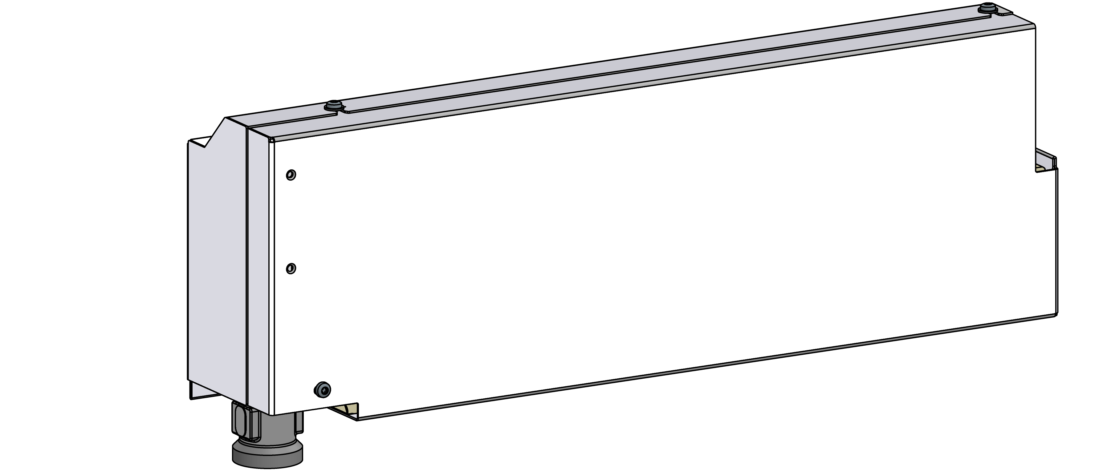
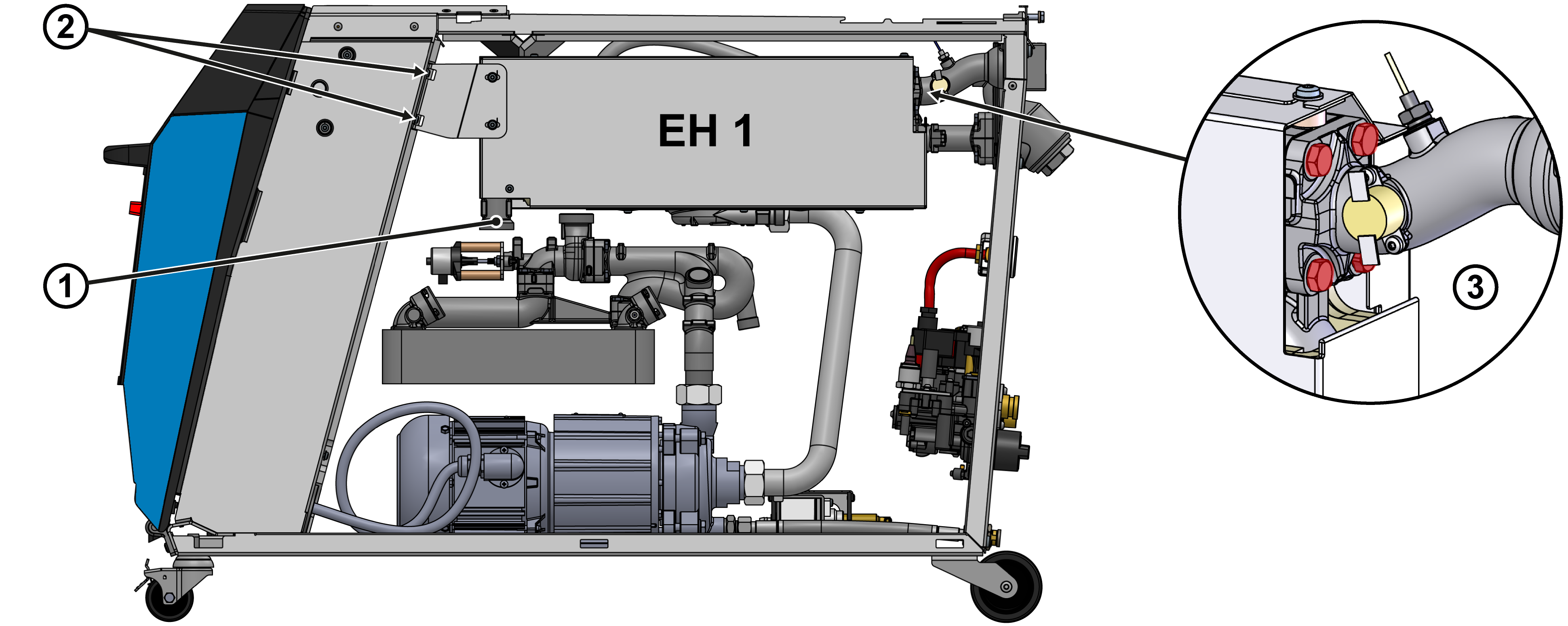
Remove the heater module (EH_1)
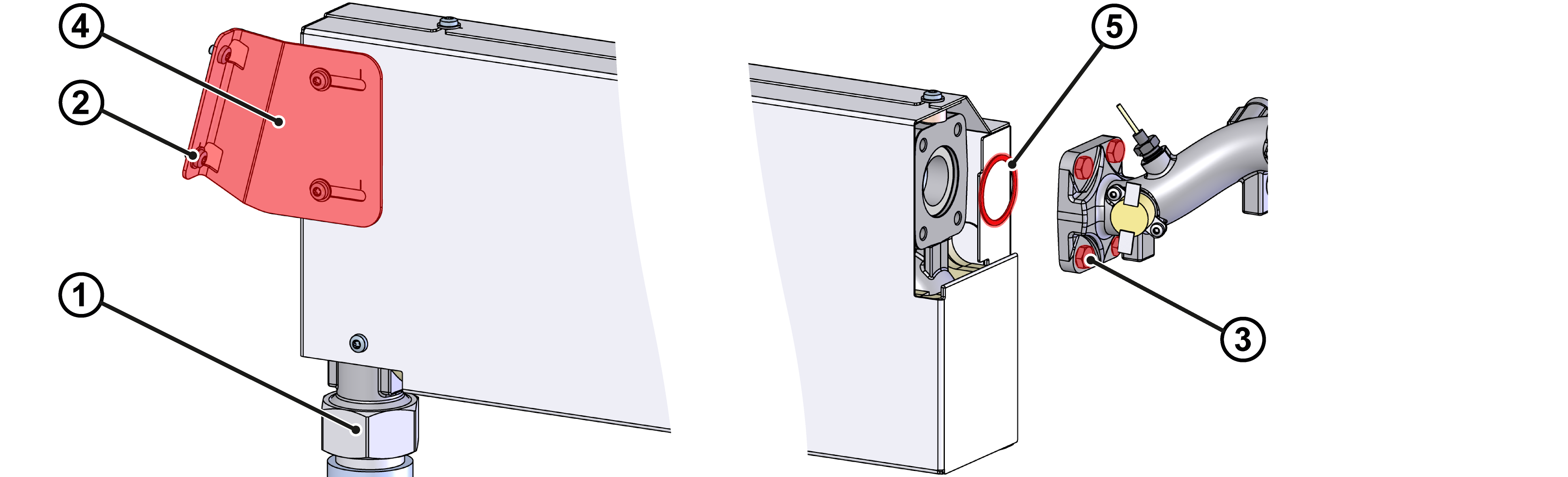
- Remove flexible tube ①. Water may escape when the connections are opened.
- Remove Torx screws ② from the bracket ½ turn.
- Remove and remove the hexagonal screws ③ from the connection flange.
- Lift the heater module (EH_1) out of the keyhole attachment and set it aside.
Install heater module (EH_1)
ATTENTION!
Screw connections, in particular combinations of stainless steel/stainless steel or steel/stainless steel, tend to get stuck or get stuck when operation for a long time at high temperatures. That's why:
Use appropriate lubricants
- Remove the bracket ④ and transfer it to the new Heating.
- Check the PTFE seal ⑤ for wear and replace if necessary.
- Insert the PTFE seal ⑤ into the groove of the new Heating.
- Connect the heater module (EH_1) to the keyhole attachment on the side of the electrical housing and position it correctly.
- Check that the seal fits neatly in the groove.
- Install the hexagonal screws ③ on the connection flange and tighten.
- Tighten the Torx screws ② from the bracket.
- Install and tighten the flexible tube ①.
Connect the cable / Attach the nameplate
- Place the heating cable into the electrical housing.
- Connect the X302.X and X303.X connectors to the ZSM-61 current measurement board:
- 400/460 V: X302.X, X303.X → A 8.1 (ZSM-61)
- 220 V: X302.X, X303.X → A 8.1 / A 8.2 (ZSM-61)
- Fold up the front and secure 2x Torx screws.
Check tightness / function
- Re-install external hydraulic connections on the Main line (OUT) and Return line (IN).
-
Switch on the unit using the I/O button (
 ), check the tightness and function of the unit.
- After a successful tightness test, heat up the temperature control unit to the maximum device temperature.
Switch off / install covers
- On the basic screen, tap the function button (
 ).
).- The unit cools down until the temperature is lower than the cooling temperature. The unit then switches off.
- Switch off the main switch (QS 1).
- Re-attach covers from the unit (→ Open unit).