PDF
Download PDF
Download page T29214 ZE external sensor retrofit.
T29214 ZE external sensor retrofit
Qualification
Qualified personnel
Material
| Pos. | Designation | article | number |
|---|---|---|---|
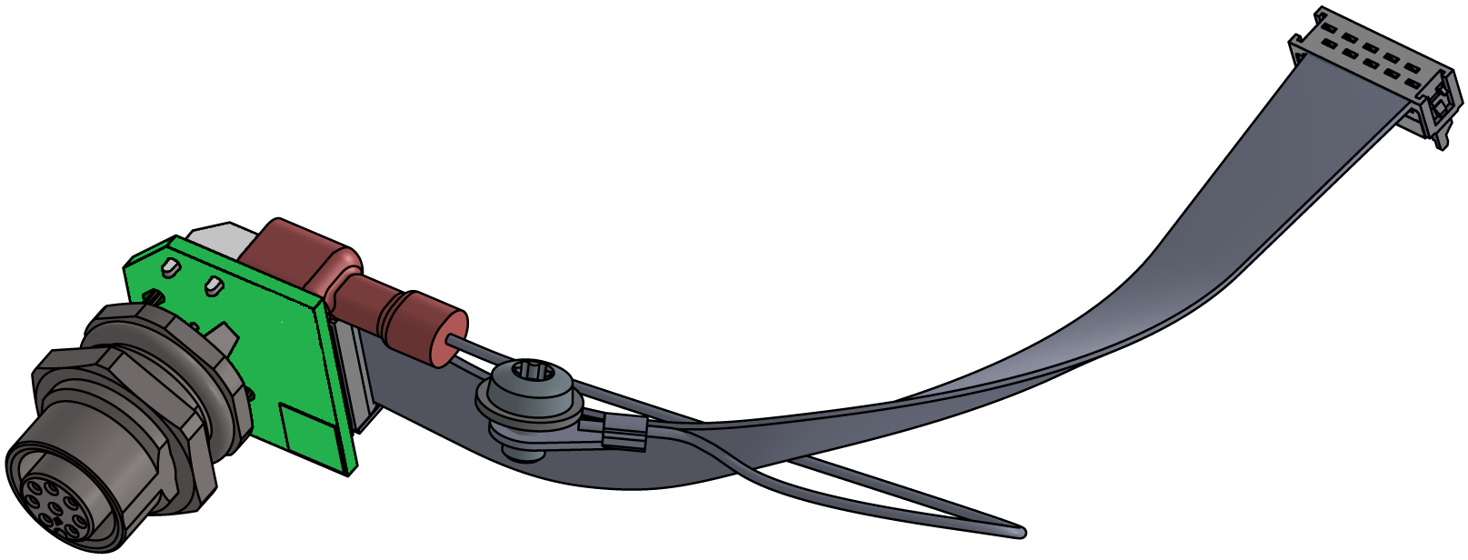
| 01 | ZE-61 board | T28578 | 1 |
| 02 | 10-pin flat cable | T28845 | 1 |
| 03 | GNYE wire | L0708 | 1 |
| 04 | Clamping disc | T14219-4 | 1 |
| 05 | M4x6 screw | B3061615 | 1 |
| 06 | M12 plug, 8-pin | T26321 | 1 |
| 07 | Nameplate | T19277 | 2 |
Required material
- Torx screwdriver size 20
- Ring spanner, size 18
Procedure
ATTENTION!
Working with the unit requires knowledge of the safety instructions and quick guide. That's why:
Read the safety instructions and quick guide carefully before starting any work. The basic requirement for safe work is compliance with all safety instructions and careful action by qualified qualified personnel to prevent accidents involving personal injury and property damage.
Cool down and turn off the unit
- On the basic screen, tap the function button (
 ).
).
→ The unit cools down until the temperature is lower than the cooling temperature. The unit then switches off.
- Switch off the main switch (QS 1), pull out the mains-connector.
Open front
- Open the front door and fold the front completely down by loosening the two Torx screws.
Retrofitting
- Remove the blind plug from the appropriate connection to the additional equipment.
→ Blind plugs are no longer required.
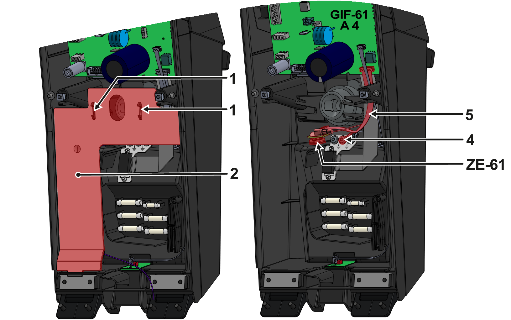
- Press the mounting straps (1) together and remove the cable cover (2).
- Insert the ZE-61 board from the inside of the front into the appropriate opening and secure it from the outside with the hexagonal nut.
→ Remove the hexagonal nut from the ZE-61 board connector first. - Connect the ground connection (L0708) with a flat plug to the ZE-61 board.
- Secure the ground connection (L0708) to the grounding plate (4) using a clamping disc and screw.
→ Make sure that all plug connections are correctly attached (see electrical circuit diagram). - Connect the flat cable (5) to the ZE-61 and GIF-61 board (A 4, slot X23).
- Insert the cable cover (2) into the appropriate recesses.
→ Make sure that the mounting straps (1) are snapped in place.
Close front
- Fold up the front and secure 2x Torx screws.
- Place new type plates on the rear wall and on the inside of the front door of the unit.
- Close the front door.
Check function
- Connect the mains-connector and switch on the main switch (QS 1).
→ initialisation starts and automatically recognizes the additional ZE equipment. - Check the recognition of additional equipment. Tap on the status field (
 ) to open the info system. General device information and available additional equipment are displayed here.
→ If this act not the case, check all plug connections again and restart the unit. -
Switch on the unit using the I/O button (
 ), check the tightness and function of the unit.
- Check the functionality of the additional equipment by connection an external sensor (see Installation and Settings).
-
Switch off the unit using the I/O button ().
→ The unit switches off and, if necessary, is cooled and depressurised. - Switch off the main switch (QS 1).