Download PDF
Download page Safety instructions / Quick guide Beer-6.
Safety instructions / Quick guide Beer-6
HB-Therm®
Safety instructions and quick guide
Beer tap Beer-6
EN (Translation of original instructions)
General
Read these instructions carefully before starting any work. The basic prerequisites for working safely are compliance with all safety instructions and prudent action by qualified personnel in order to avoid accidents that lead to personal injury / property damage.
Safety instructions are marked with symbols:
Danger! / Warning! / Caution!
![]() ... indicates a hazardous situation which, if disregarded, may result in injury (Caution!) or serious or fatal injury (Warning!, Danger!).
... indicates a hazardous situation which, if disregarded, may result in injury (Caution!) or serious or fatal injury (Warning!, Danger!).
Danger due to electric shock!
![]() ... if disregarded, there is a risk of serious or fatal injury.
... if disregarded, there is a risk of serious or fatal injury.
Hot surface!
![]() ... failure to comply may result in minor to severe burns.
... failure to comply may result in minor to severe burns.
Attention!
![]() ... indicates a potentially hazardous situation which, if disregarded, may result in property damage.
... indicates a potentially hazardous situation which, if disregarded, may result in property damage.
Make sure that these instructions are accessible at all times in the immediate vicinity of the unit.
Further instructions are available at https://knowledge.hb-therm.eu, see Chapter 6. If you have any questions or if anything is unclear, please contact your country representative (see type plate) or our customer service www.hb-therm.com.
Designation use
The Beer-6 unit is designed exclusively for dispensing beer from suitable kegs. Gas pressure (CO2) is used to transport the beer from the keg through the continuous flow dry cooler to the tap at the front of the unit.
The unit consists of a continuous flow dry cooler and a tap. The continuous flow dry cooler is designed to cool beer that has already been produced and delivered in kegs. The beer is transported from the keg into the continuous flow dry cooler using gas pressure (CO2) and then on to the tap.
The Beer-6 unit is designed and constructed exclusively for the specified values according to the type plate. Claims of any kind due to improper use are excluded.
General safety instructions
![]() Observe local, legal and company safety regulations and requirements.
Observe local, legal and company safety regulations and requirements.
![]() Regularly check the entire system for leaks or damage. Check the hose lines and screw connections for tightness. Remedy any defects immediately.
Regularly check the entire system for leaks or damage. Check the hose lines and screw connections for tightness. Remedy any defects immediately.
![]() Always keep these instructions and all information on the unit clearly legible. Replace damaged or illegible information immediately.
Always keep these instructions and all information on the unit clearly legible. Replace damaged or illegible information immediately.
![]() Never override safety devices.
Never override safety devices.
![]() In the event of uncontrolled faults, set the mains switch to the O position and disconnect the unit from the power supply.
In the event of uncontrolled faults, set the mains switch to the O position and disconnect the unit from the power supply.
![]() Disconnect the unit from the power supply when opening it.
Disconnect the unit from the power supply when opening it.
![]() Perform cleaning after each use.
Perform cleaning after each use.
![]() Cleaning and maintenance work may only be carried out by qualified personnel.
Cleaning and maintenance work may only be carried out by qualified personnel.
![]() Only use original spare parts from the manufacturer.
Only use original spare parts from the manufacturer.
![]() Only operate the unit when the drip tray and storage rack are positioned under the tap.
Only operate the unit when the drip tray and storage rack are positioned under the tap.
Transport and packaging
Check the delivery immediately on receipt for completeness and for any transport damage.
![]() Transporting, crane and lifting equipment must be suitable and operated by qualified personnel.
Transporting, crane and lifting equipment must be suitable and operated by qualified personnel.
![]() For transportation purposes, the unit must be completely empty.
For transportation purposes, the unit must be completely empty.
![]() For careful handling and in-plant transport, observe the symbols and instructions on the packaging.
For careful handling and in-plant transport, observe the symbols and instructions on the packaging.
![]() To protect the unit, do not remove the packaging until shortly before installation.
To protect the unit, do not remove the packaging until shortly before installation.
![]() When shipping a unit, use only the original or equivalent packaging. Only transport the unit upright.
When shipping a unit, use only the original or equivalent packaging. Only transport the unit upright.
Procedure for carrying by crane
![]()
- Pull out the lifting device at the rear of the unit.
- Attach lifting straps to the lifting device and to the front handle.
Installation
![]() Remove the protective film from the display.
Remove the protective film from the display.
Installation conditions
| Unit location | water-protected indoor area |
| sufficiently good ventilation | |
| Max. installation altitude | 3000 m above sea level |
| Installation area | horizontal, stable and low-vibration surface |
| Permissible ambient temperature | 16–40 °C |
| Relative Humidity | 35–85 % RH (nicht kondensierend) |
| Secure units | Lock the brake on the front castors. Secure units on elevations to prevent them from falling. |
| Mains switch | Access at any time |
| Mains connection cable | The mains connection cable of the device must not come into contact with any cables or parts whose surface temperatures exceed 50 °C. |
Connections
![]() Only use suitable connections, screw connections and hose lines.
Only use suitable connections, screw connections and hose lines.
![]() There are various tap head systems available. The system that fits the barrel must be used.
There are various tap head systems available. The system that fits the barrel must be used.
![]() The beer hose and tap are included in the scope of delivery. The remaining components are country-specific and can be obtained from your beer supplier.
The beer hose and tap are included in the scope of delivery. The remaining components are country-specific and can be obtained from your beer supplier.
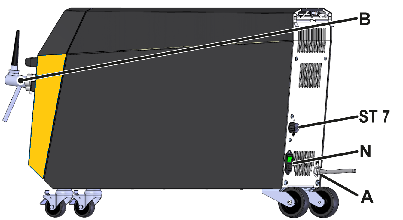
| A | Beer inlet (IN) | |
| B | Beer tap (OUT) | |
| ST 7 | Thermostat (temperature control) | |
| N | Power switch with power cable | Mains voltage U (see type plate) |
| Maximum pre-fuse Imax (see type plate) | ||
Prepare the tap system
![]() Place the carbon dioxide cylinder upright, secure it against falling over and never place it near a heat source. Observe the instructions on the pressure cylinder.
Place the carbon dioxide cylinder upright, secure it against falling over and never place it near a heat source. Observe the instructions on the pressure cylinder.
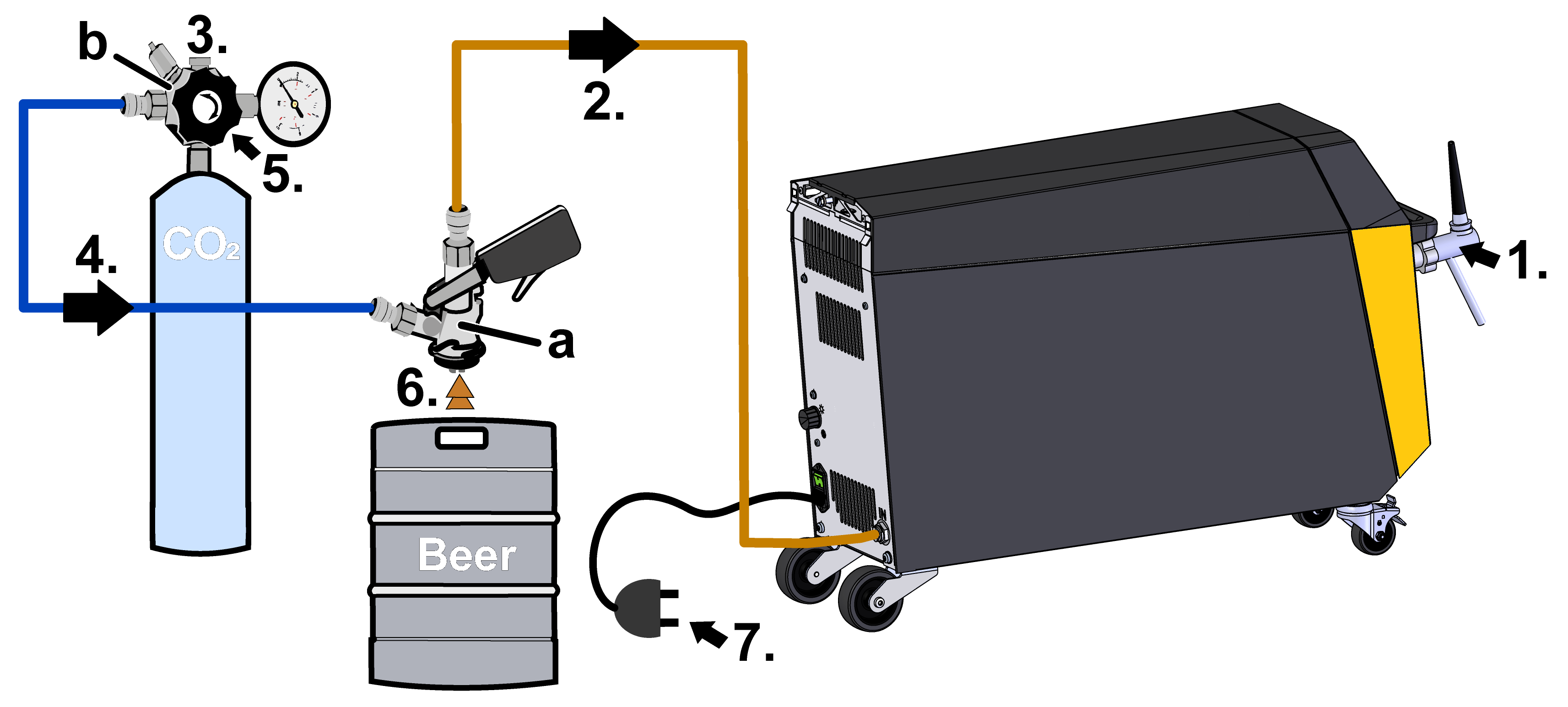
![]() Prepare and switch on the tap system early so that the cooler can reach the necessary operating temperature
Prepare and switch on the tap system early so that the cooler can reach the necessary operating temperature
- Connect the tap to connection B (OUT).
- Connect connection A (IN) and the tap head (a) to the beer hose.
- Connect the pressure reducer (b) to the CO2 cylinder.
- Connect the pressure reducer (b) and the tap head (a) to the CO2 hose.
- Open the CO2 valve.
- Connect the tap head (a) to the beer keg.
- Connect to the mains power supply.
Commissioning
![]() When initially starting-up, all electrical connections must be checked.
When initially starting-up, all electrical connections must be checked.
Switching On/Off
The Beer-6 unit is switched on and off via the power switch at the bottom of the rear panel.
As soon as the unit is connected to the power supply, it begins to initialise. The display shows a still image. There are no functions for the unit on the display.
Adjusting the gas pressure
Adjust the gas pressure using the pressure adjustment screw on the pressure reducer. Briefly pull the ring on the safety valve so that the correct value is displayed on the pressure gauge.
![]() The optimum gas pressure for beer is defined by the beer supplier (manufacturer). The required gas pressure depends on the temperature and CO2 saturation of the beer. The optimum dispensing pressure is between 1,5 and 3 bar.
The optimum gas pressure for beer is defined by the beer supplier (manufacturer). The required gas pressure depends on the temperature and CO2 saturation of the beer. The optimum dispensing pressure is between 1,5 and 3 bar.
Adjusting the cooling
The thermostat on the back of the appliance can be used to set the temperature of the beer to between 4–10 °C. Position ![]() on the thermostat means the lowest cooling capacity and therefore the highest outlet temperature of the beer. Position
on the thermostat means the lowest cooling capacity and therefore the highest outlet temperature of the beer. Position ![]() means the highest cooling capacity and therefore the lowest outlet temperature of the beer.
means the highest cooling capacity and therefore the lowest outlet temperature of the beer.
Tapping beer
![]() Ensure that the valve on the pressure cylinder and all taps in the CO2 line are open.
Ensure that the valve on the pressure cylinder and all taps in the CO2 line are open.
![]() Do not pour beer into warm glasses.
Do not pour beer into warm glasses.
![]() If excessive foaming occurs, increase the pressure at the pressure reducer or connect the beer to the dispensing system when chilled.
If excessive foaming occurs, increase the pressure at the pressure reducer or connect the beer to the dispensing system when chilled.

- Hold the glass at an angle under the tap and pull the tap fully forward.
- Once the glass is full, return the tap to the middle position. If necessary, the head of foam can be topped up using the foam function (push the tap backwards).
- Cheers!
Maintenance / Care
In the event of intensive use, the required maintenance intervals should be shortened accordingly.
| Interval | Component | Maintenance work | Qualification |
| Daily or after use | Tap including pipes | Rinse with clean water after last use | Operator |
| Monthly | Circulation system | Chemical cleaning | Operator |
| Quarterly | Compressor | Clean with brush | Qualified hydraulic personnel |
| Blow through with compressed air (gas) | |||
| Every 1 ½ years | Hydraulic hose lines | Check for damage to the outer sheath and in the sealing area. Replace if necessary. | Qualified hydraulic personnel |
| Electrical wiring | Check the electrical wiring for damage to the outer sheath. Replace if necessary. | Qualified electrician |
Knowledge
Go to Knowledge home page for general information

| Overvoltage category | II |
| Degree of contamination | 2 |
The type plate is located on the rear panel of the unit and on the inside of the door.
The following information can be taken from the type plate:
- Type
- Unit number
- Additional
- Connection values
- Year of manufacture
- Protection class
- Manufacturer
- Service point