Download PDF
Download page HB-100/140/160Z62 data.
HB-100/140/160Z62 data
| Basic data | |||
|---|---|---|---|
| Type | HB-100Z62 | HB-140Z62 | HB-160Z62 |
| Temperature max. | 100 °C | 140 °C | 160 °C |
| Circulating volume in unit (approx.) | 2,0 L | ||
| Dimensions (height/width/depth) → Dimensions | 650 mm / 300 mm / 991 mm | ||
| Weight max. | 73 kg | 78 kg | |
| Environment | |||
| Temperature range | 5–40 °C | ||
| Relative humidity | 35–85 % RH(non-condensing) | ||
| Continuous sound pressure level | <70 dB(A) | ||
Surface temperature (back of the unit) | >55 °C | ||
| Cleanroom capability | «At Rest» <ISO Klasse 6 (Kl. 1000) «In Operation» ISO Klasse 7 (Kl. 10 000) | ||
| Temperature measurement | |||
Resolution Control accuracy Tolerance | 0,1 °C ±0,1 °C ±0,8 °C | ||
| Flow rate measurement | |||
measuring range resolution Tolerance | 0,4–60 L/min 0,1 L/min ± (5% of measured value + 0,1 L/min) | ||
| Pressure measurement | |||
Measuring range Resolution Tolerance | 0–20 bar 0,1 bar ± 5% of of rated value | ||
| Pump pressure indicator | |||
| Tolerance | ±10% of rated value | ||
| Hydraulic data | |||
|---|---|---|---|
| Connection | HB-100Z62 | HB-140Z62 | HB-160Z62 |
| Main line, Return line | |||
Thread Resistance (including external heat transfer circuit) | G3/4 20 bar, 120 °C | G3/4 20 bar, 160 °C | G3/4 20 bar, 180 °C |
| Cooling water | |||
Pressure Thread Resistance | 2–5 bar G3/8 10 bar, 100 °C | ||
| Separate cooling water | |||
Pressure Thread Resistance | 2–5 bar G1/4 10 bar, 100 °C | ||
| compressed air (additional equipment ZG) | |||
Pressure Thread Resistance (including external heat transfer circuit) | 2–5 bar G1/4 10 bar, 100 °C | ||
* Mould emptying is more efficient with higher compressed air
| Electrical data | |||
|---|---|---|---|
| Residual current circuit-breaker | We recommend using a type B residual current circuit breaker (RCD), as the temperature control units are equipped with a frequency converter. Type A RCD are not suitable. The leakage current is max. 5 mA per unit. | ||
| Mains cable to unit | 3LPE, 4 m (im Standard) H07RN-F (Standard) / H07BQ-F (CE) SO/SOW/SOOW (UL/CSA) | ||
| Cross-section | 400/460 V, 8 kW: 4x2,5 mm2 (CE) / 4xAWG 12 (UL/CSA) 400/460 V, 16 kW: 4x6,0 mm2 (CE) / 4xAWG 10 (UL/CSA) 220 V, 8 kW: 4x6,0 mm2 (CE) / 4xAWG 10 (UL/CSA) 220 V, 16 kW: 4x16,0 mm2 (CE) / 4xAWG 4 (UL/CSA) | ||
| Network system | |||
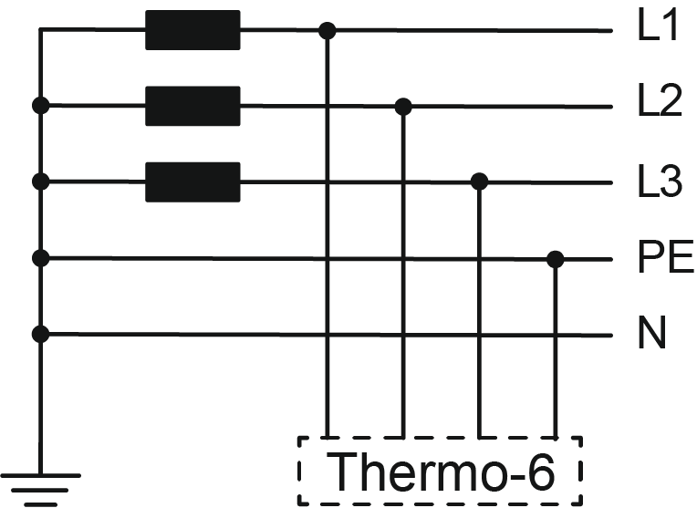
| TN-System A TN-System (network with grounded protective conductor) is common in Europe. The unit can be connected and operated with this network system without any measures. | ||
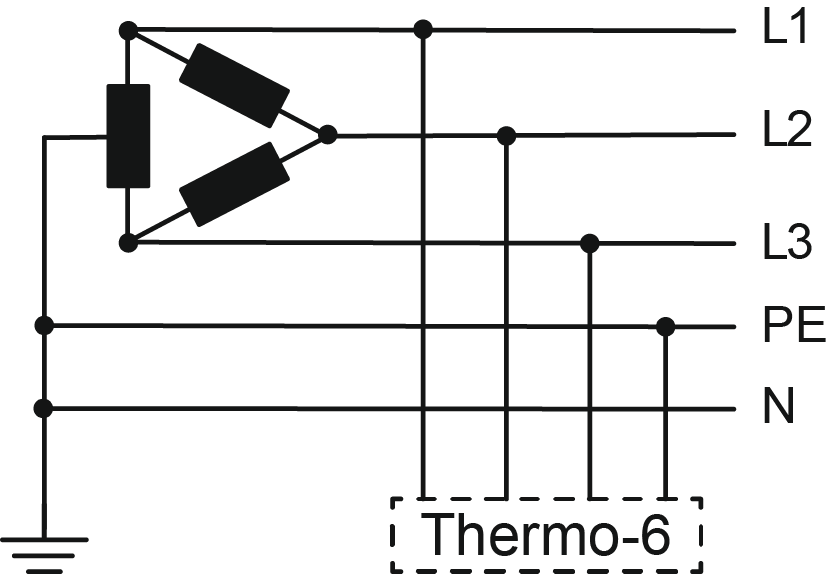
| High-Leg-Delta-System A High-Leg-Delta-System, in which a midpoint is grounded between two phases, is common in Asia and North America. Starting with software-version SW61-1_2401, The unit can be connected and operated to this network system without any measures. | ||
| Corner-Grounded-Delta-System A Corner-Grounded-Delta-System, in which one phase is grounded, is common in Asia and North America. Starting with software-version SW61-1_2401, The unit can be connected and operated to this network system without any measures. | ||
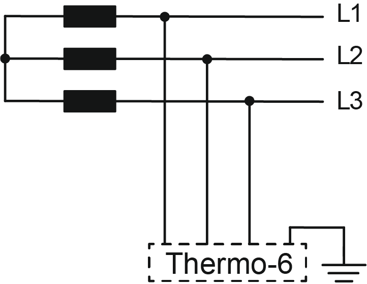
| IT-System In an IT-System where there is no galvanic connection between active conductors and grounded parts, measures are required:
operation without IT screws poses no safety risk, but EMC interference emissions can increase. Compliance with EMC limits is the responsibility of the operator. | ||
| Heating capacity | The heating capacity is valid at rated voltage (400 V, 460 V or 210 V) and varies by a maximum of ± 10% within the specified voltage range. | ||
| Mains voltage | see nameplate on the unit | ||
| Maximum fusing | see nameplate on the unit | ||
| Rated short circuit current | 6 kA | ||
| Overvoltage category | II | ||
| Degree of contamination | 2 | ||
| Protection class | IP 44 | ||