Download PDF
Download page T28500 USR-61 replacement control system.
T28500 USR-61 replacement control system
qualification
Qualified personnel
Material
| Pos. | Designation | Article | Number |
|---|---|---|---|
| 01 | USR-61 control system | T28500 | 1 |
Required material
- Torx screwdriver size 20
- Flat head screwdriver, size 0
procedure
ATTENTION!
Working with the unit requires knowledge of the safety instructions and quick guide. That's why:
Read the safety instructions and quick guide carefully before starting any work. The basic requirement for safe work is compliance with all safety instructions and careful action by qualified qualified personnel to prevent accidents involving personal injury and property damage.
Cool down and turn off the unit
- On the basic screen, tap the function button (
 ).
).
→ The unit cools down until the temperature is lower than the cooling temperature. The unit then switches off.
- Switch off the main switch (QS 1), pull out the mains-connector.
Open front
- Open the front door and fold the front completely down by loosening the two Torx screws.
Replace control system
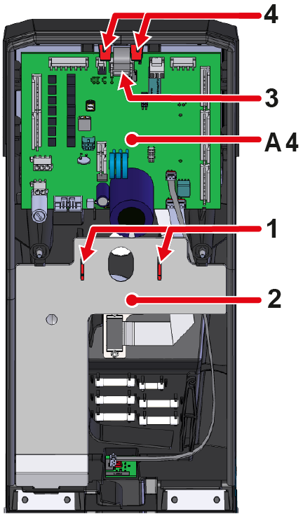
- Press the mounting clips (1) together and remove the cable cover (2).
- Remove the connector (3) on the GIF-61 (A 4) unit board.
- Push the mounting straps (4) of the GIF-61 (A 4) unit board outwards. The board can now be lifted out and folded back.
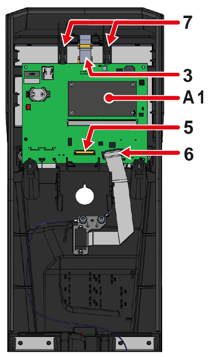
→ Connectors on the GIF-61 do not have to be removed. - Remove the cable connection (5) from the display (A 2) on the USR-61 control system (A 1).
→ The plug connection from the display must be unlocked (e.g. With a flat screwdriver) before the cable connection can be removed. - Remove the plug connection (6) from the HB CAN (X 79) connector on the USR-61 control system (A 1).
- Push the USR-61 (A 1) control system mounting straps (7) outwards. The circuit board can now be lifted out.
→ Remove the ground line cable on the back of the USR-61 (A 1) control system.
- Connect the ground cable to the back of the new USR-61 (A 1) control system.
- Insert the USR-61 (A 1) control system into the appropriate recesses.
→ Check whether the mounting straps (7) are locked in place. - Reconnect the connectors (3, 5 and 6) to the USR-61 control system (A 1).
→ Check whether all connectors are correctly attached. - Insert the GIF-61 unit board (A 4) into the appropriate recesses
→ Check whether the mounting straps (4) are locked in place. - Reconnect the plug connection (3) to the GIF-61 (A 4) unit board.
- Insert the cable cover (2) into the appropriate recesses.
→ Check whether the mounting clips (1) are locked in place.
Close front
- Fold up the front and secure 2x Torx screws.
Check function
- Connect the mains-connector and switch on the main switch (QS 1).
→ The unit carries out an automatic software-update. - Check the time zone, date, and time and set them correctly if necessary.
NOTE!
The configuration and calibration data are stored on the GIF-61 (A 4) unit board and are therefore not lost when the USR-61 (A1) control system is replaced.
-
Switch on the unit using the I/O button (
 ), check the tightness and function of the unit.
- Check the device functions (regulate for the desired set value).
-
Switch off the unit using the I/O button ().
→ The unit switches off and, if necessary, is cooled and depressurised. - Switch off the main switch (QS 1).