Download PDF
Download page Detect the cause of the fault.
Detect the cause of the fault
The upcoming fault message shows the following information:
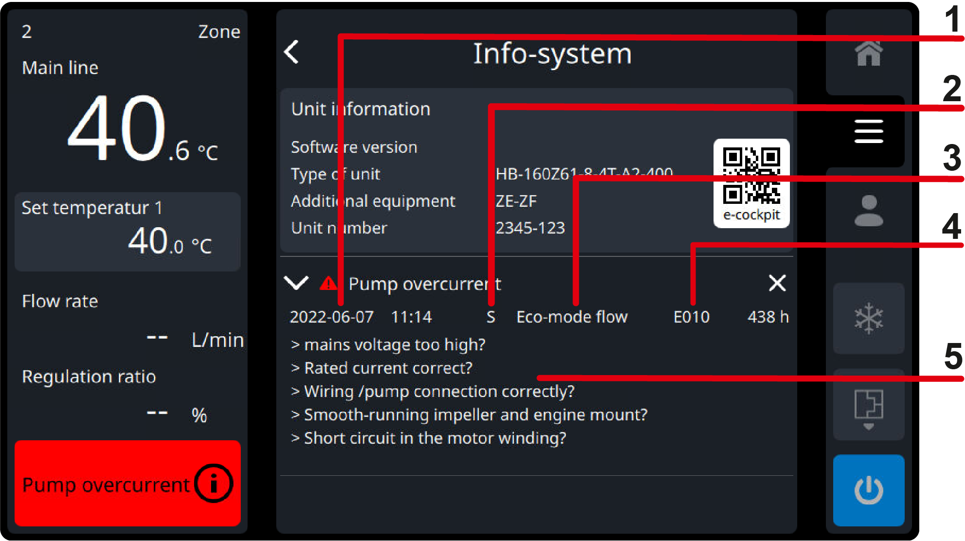
| Date/time (1) | Time at the time the fault occurred |
| Alarm type (2) | S = System alarm (operation monitoring, function monitoring, component malfunction) G = Limit value alarm (temperature monitoring, flow monitoring) W = Maintenance alert (integrated maintenance request) |
| operating mode (3) | Operating mode at the time the fault occurred |
ID (4) | Fault ID |
| Assistance (5) | Help text for the alarm with possible causes of malfunction |
Disturbance overview
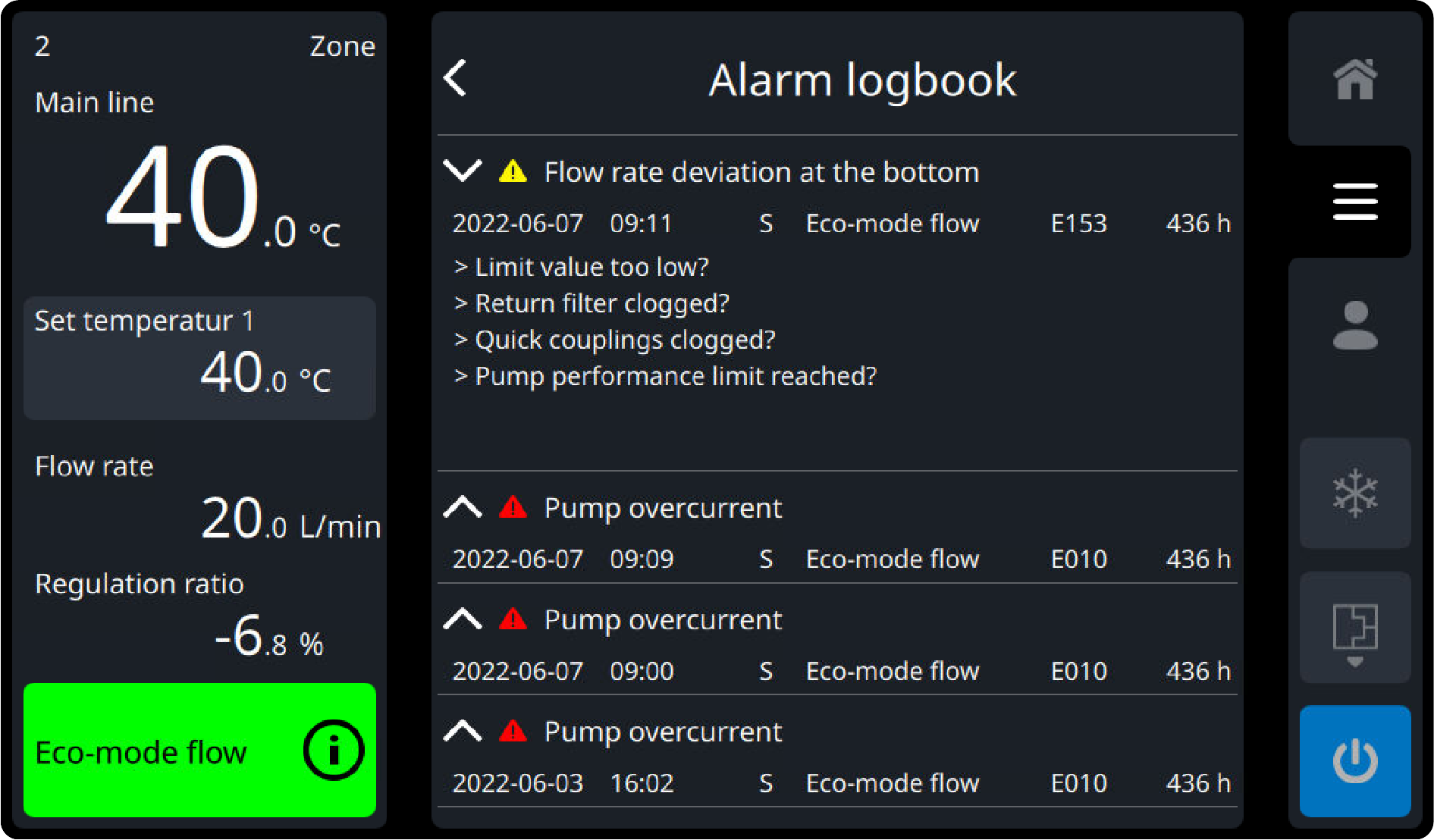
The last 100 fault messages that occurred can be displayed as follows:
- Select [Alarm Logbook].
Select the desired fault message.
- Tap on the button (
 ) to open and display the fault message.
NOTE!
The fault messages are sorted according to the time the fault occurred (last fault at the top).
commissioning after the fault has been resolved
After the fault has been rectified, the following steps must be carried out to restart:
- Reset emergency stop devices.
- Acknowledge the fault by tapping the button (
 ) or by swiping to the left.
 - Make sure there are no people in the hazardous area.
- Start up The unit in accordance with the instructions in the Quick operation Guide.
Disturbance table
ID | fault | Alert level | Possible cause |
|---|---|---|---|
E010 | pump overcurrent | 33 |
|
E012 | ZSM overcurrent heating | 33 |
|
E013 | ZSM undercurrent heating | 13 |
|
E014 | phase missing frequency converter | 33 |
|
| E014.1 | Phase missing L1 | 33 |
|
E016 | Frequency converter error | 33 |
|
E017 | ZSM solid-state relay fault | 35 |
|
E018 | ZSM internal error | 30 |
|
E020 | Temperature limit | 5 |
|
E021 | Overtemperature circuit | 33 |
|
E022 | sensor failure main line | 30 |
|
E023 | sensor failure return line | 30 |
|
E024 | sensor failure external | 10 |
|
E025 | External sensor failure comp. | 10 |
|
E026 | sensor failure cooler | 10 |
|
E030 | System pressure too high | 20 |
|
E031 | System pressure too low | 33 |
|
E032 | sensor failure pressure BP 1 | 33 |
|
E033 | sensor failure pressure BP 2 | 33 |
|
| E035 | hose rupture | 33 |
|
E036 | sensor failure pressure BP 3 | 10 |
|
E041 | initial fill period exceeded | 33 |
|
E042 | Refill volume exceeded | 33 |
|
| E045 | Leak stop interrupted | 33 |
|
E050 | Flow rate zero | 33 |
|
E051 | invalid flow rate | 33 |
|
| E052 | GIF-DMS communication error | 33 |
|
E060 | GIF-USR communication error | 33 |
|
| E061 | Communication failure Flow | 33 |
|
| E062 | Remote cable unplugged | 13 |
|
E065 | communic. Disturbed FU | 33 |
|
E066.n | communication disturbed ZSM | 30 |
|
E067 | Pump speed is below | 33 |
|
| E068 | no gate connection | 13 |
|
| E069 | Multiple Gate-6 found | 13 |
|
| E072 | remote address conflict | 11 | Several Thermo-6 units with the same remote control address were found in the network.
|
| E073 | address conflict Flow | 11 | Several flow meter with the same identification and the same address range were found.
|
| E075 | Overtemperature Gate-6 | 13 |
|
| E079 | Database faulty | 03 | The historical data database is faulty. The data can no longer be saved, displayed, or exported. The system must be rebooted to troubleshoot. The database is automatically deleted and re-created.
|
E080 | undercurrent step motor KV 1 | 10 |
|
E081 | undercurrent step motor KV 2 | 10 |
|
E082 | Overcurrent step motor KV 1 | 30 |
|
E083 | Overcurrent step motor KV 2 | 30 |
|
E087 | Fan speed fell below | 13 |
|
E088 | Main contactor control KM 1 | 33 |
|
| E089 | Overtemperature electrical part | 13 |
|
| E095 | Update error GIF | 33 |
|
| E096.n | ZSM update error | 33 |
|
| E097 | Soft-/hardware incompatible | 33 | The software is not compatible with the hardware-version GIF-61.
The latest software can be purchased via the e-cockpit mobile app or from the HB-Therm country representative. |
| E098 | Soft-/hardware incompatible | 33 | The software is not compatible with the ZSM-61 hardware-version.
The latest software can be purchased via the e-cockpit mobile app or from the HB-Therm country representative. |
| E099 | Invalid configuration | 31 |
|
| E120 | upper temperature deviation | 10 |
|
| E121 | lower temperature deviation | 10 |
|
| E122 | return/main difference | 10 |
|
| E124 | Temperature difference deviation | 13 |
|
| E150 | flow rate too big | 10 |
|
| E151 | flow rate too low | 10 |
|
| E152 | flow rate deviation above | 10 |
|
| E153 | flow deviation below | 10 |
|
| E201 | maintenance pump | 13 | The maintenance interval for the pump has been exceeded.
(Until then, the warning icon will be displayed in the tab bar of the standard display) |
| E203.1 | Heating maintenance | 13 | The maintenance interval for the Heating has been exceeded.
(Until then, the warning icon will be displayed in the tab bar of the standard display) |
| E204 | maintenance cooler | 13 | cooler maintenance interval exceeded
(Until then, the warning icon will be displayed in the tab bar of the standard display) |
| E206 | maintenance cooling water filter | 13 | The maintenance interval for the cooling water filter has been exceeded.
(Until then, the warning icon will be displayed in the tab bar of the standard display) |
| E207 | maintenance return line filter | 13 | The maintenance interval for the return line filter has been exceeded.
(Until then, the warning icon will be displayed in the tab bar of the standard display) |
| E208 | maintenance fan | 13 | The fan maintenance interval has been exceeded.
(Until then, the warning icon will be displayed in the tab bar of the standard display) |
| E210 | maintenance fill valve | 13 | The maintenance interval for the filling valve has been exceeded.
(Until then, the warning icon will be displayed in the tab bar of the standard display) |
| E211 | maintenance air relief valve | 13 | The maintenance interval for the air relief valve has been exceeded.
(Until then, the warning icon will be displayed in the tab bar of the standard display) |
| E301 | Filling valve not recognized | 33 |
|
| E302 | air relief valve not recognized | 33 |
|
| E310 | Voltage 15 VAC is missing | 33 |
|
E311, E312, E313, E314 | Voltage xx VDC outside Tolerance | 03 |
|
| E900.nn | flow rate too low (external flow meter) | 10 |
|
| E901.nn | flow rate too big (external flow meter) | 10 |
|
| E902.nn | return/main difference (external flow meter) | 10 |
|
| E903.nn | sensor failure return line (external flow meter) | 10 |
|
| E904.nn | sensor failure main line (external flow meter) | 10 |
|
Background information on possible causes of faults
The unit is directly disconnected from the Mains voltage during heating
Cause of the rise in temperature
The main line temperature rises sharply if the unit was heating at the time it was switched off (positive regulation ratio). Regardless of what caused the switch off (with/without pressure relief, mould evacuation, fault, main switch OFF or power failure). This rise in temperature is due to the stored energy in the heating system. Without circulation from the heat transfer medium (unit switched off), the water in the Heating absorbs the heat from the Heating. This behavior is physically determined and cannot be prevented, but only minimized.
The heating of the Thermo-6 units can store more energy than that of the Thermo-5 units, resulting in a higher temperature rise in the flow.
Depending on the main line temperature at which the unit is switched off and how high the Heating Capacity (positive regulation ratio was when switch off, the following error messages may occur:
- edition error message E020 (temperature limit) main line
temperature rises above the set limiting temperature +5 K. After the unit is switched on, it only starts heating when the temperatures (Main line, Return line and, if available, external) are lower than the set limiting temperature +5 K. - edition error message E021 (overtemperature circuit) main line
temperature rises until the ST 1 temperature limiter triggers in the Main line. The unit can only be switch on again when the temperature in the Main line falls below the reset temperature of the ST 1 temperature limiter.
Possible measures
- Avoiding uncontrolled shutdown due to abrupt interruption of the power supply (e.g. By main switch OFF)
- Reducing the safety cooling temperature or mould evacuation temperature:
→ Select [Set values] > [Safety cooling temperature].
→ Select [Setting] > [Miscellaneous] > [Mould Evacuation Temperature].
As a result, this first cools down to the set value before it switches off or starts emptying the mold. Active Cooling Before The Unit Is Switch Off Reduces The Stored Energy In The Heating And Thus Also Reduces The Temperature Rise In the flow.
Evaporation in the Return line with a small cross section
Cause of evaporation
If a component (nipple, coupling, etc.) whose inner diameter is small¹ is installed at the return connection, the water may evaporate due to a high flow rate. The resulting vapor bubbles interfere with the Flow rate measurement. As a result, individual incorrect measurements can occur up to a total failure of the Flow rate measurement.
With Thermo-6 units, this topic is the same as with Thermo-5 units. However, the Thermo-6 unit has a higher flow rate than the comparable Thermo-5 unit. For this reason, the majority of these problems are only found with the Thermo-6 unit.
¹ The diameter should be considered together with the flow rate. The flow rate can be calculated using the following formula:
→ flow rate [m/s] ≈ (flow [L/min] ÷ diameter [mm²]) × 21
If the flow rate is in the range of 10 m/s or higher, evaporation in water is possible.
In the case of couplings in particular, care should be taken that the term “DNx” does not necessarily correspond to the inner diameter of the flowing water (example: self-closing Hasco coupling DN9 has an inner diameter of 3-4 mm)! This is often significantly smaller. Especially with self-closing couplings, there are additional constrictions due to the built-in check valves.
Users who test the units in the service point using quick couplings (small cross section) and a direct connection between Main line and Return line could observe this behavior (many incorrect measurements or total failure of the Flow rate measurement).
Recognition
- Constriction/small quick couplings at the return line
- Many vents (created due to incorrect Flow rate measurement measurements)
- invalid flow rate alarm (E051)
Possible measures
- Remove constriction on Return line (recommended)
- Reduce flow rate by reduction pump speed (if removal of constriction cannot be implemented)
Evaporation due to clogged filter screen
As with “evaporation in the Return line with small cross-sections,” a clogged filter screen can also lead to a very high flow rate. The scenario is the same.
Recognition
- with additional ZF equipment: filter screen maintenance >100%
Possible measures
- Clean the filter screen on the return line
- Shorten the maintenance interval (without additional ZF equipment):
→ Select [Service] > [Parameter] > [Maintenance] > [Return Line Filter Limit factor]