Download PDF
Download page T24426, T24427, T24683: Contactor.
T24426, T24427, T24683: Contactor
purpose
Electrical contactor replacement (KM 1)
qualification
Qualified electrical personnel
Material
| Pos. | Designation | T24426 | T24427 | T24683 |
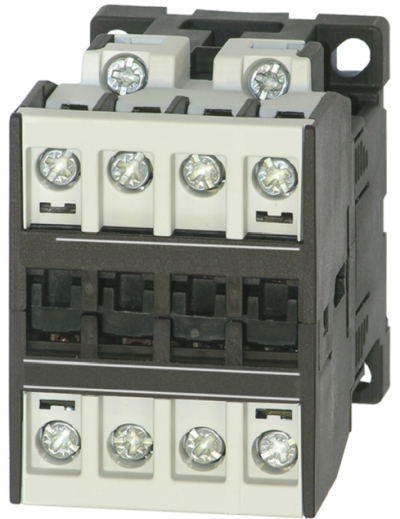
| 01 | Contactor K3-10, 24 VAC | 1 | - | - |
| 01 | contactor K3-18, 24 VAC | - | 1 | - |
| 01 | contactor K3-32, 24 VAC | - | - | 1 |
Required material
- Torx screwdriver size 20
- Flat head screwdriver, size 3
procedure
ATTENTION!
Working with the unit requires knowledge of the safety instructions and quick guide. That's why:
Read the safety instructions and quick guide carefully before starting any work. The basic requirement for safe work is compliance with all safety instructions and careful action by qualified qualified personnel to prevent accidents involving personal injury and property damage.
cooling / switch off
- On the basic screen, tap the function button (
 ).
).- The unit cools down until the temperature is lower than the cooling temperature. The unit then switches off.
- Switch off the main switch (QS 1), pull out the mains-connector.
Open front
- Open the front door and fold the front completely down by loosening the two Torx screws.
- Remove the protective cover in the electrical housing by removing the Torx screws.
Replace spare part
NOTE!
Make sure that all cable markings are easy to read before replacement. If necessary, re-label the cable. The connection is made according to the electrical circuit diagram of the respective device type (click here... ).
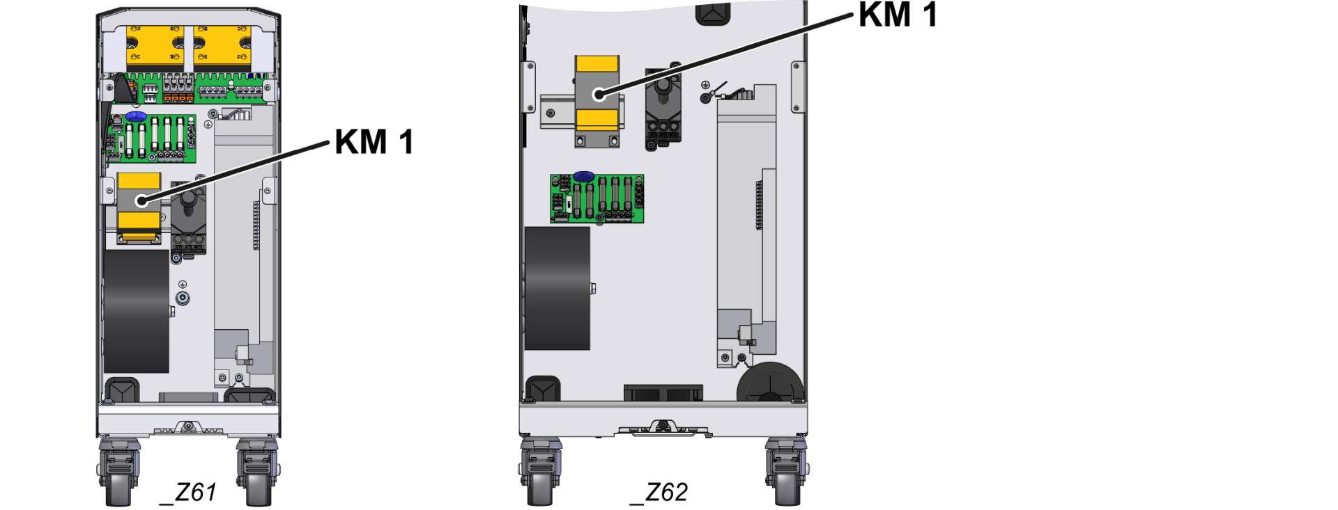
- Remove all cable from the KM_1 contactor terminals.
- Remove the contactor (KM_1) from the hat rail.
- Release the lock on the bottom of the contactor with a slotted screwdriver.
- Tilt the protector slightly and lift it off the hat rail.
- Check whether the new contactor (KM_1) is suitable for the intended use (compare technical specifications).
- Install the new contactor (KM_1) on the hat rail.
- contactor protector so that the lock is facing downwards. Place on the hat rail and press down until you hear a “click.”
- Connect the cable to the correct terminals in accordance with the electrical circuit diagram.
- Make sure that no cable insulation is jammed and that the cable contact is flat in the connection chamber.
- Tighten cable connections with a torque of 10 Nm.
- Perform a visual and tensile test.
- Make sure that all cable connections are securely fastened and correctly manufactured according to the electrical circuit diagram.
Close front
- Install the protective cover around the electrical housing and secure with Torx screws.
- Fold up the front and secure 2x Torx screws.
Check function
- Connect the mains-connector and switch on the main switch (QS 1).
-
Switch on the unit using the I/O button (
 ), check the tightness and function of the unit.
-
Switch off the unit using the I/O button ().
- The unit switches off and, if necessary, is cooled and depressurised.
- Switch off the main switch (QS 1).