Download PDF
Download page T25305-X: Pressure sensor.
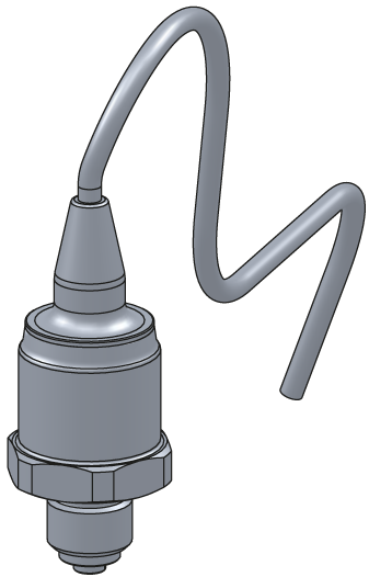
T25305-X: Pressure sensor
purpose
Replacing the pressure sensor (BP 1, BP 2, BP 3)
qualification
Qualified personnel
Material
| Pos. | Designation | article | T25305-X |
| 01 | pressure sensor 0–25 bar | T25305-X | 1 |
| 02 | O-ring 7,5x2 – FPM (optional) | T28662 | 1 |
Required material
- Torx screwdriver size 20
- cable tie
procedure
ATTENTION!
Working with the unit requires knowledge of the safety instructions and quick guide. That's why:
Read the safety instructions and quick guide carefully before starting any work. The basic requirement for safe work is compliance with all safety instructions and careful action by qualified qualified personnel to prevent accidents involving personal injury and property damage.
cooling / drain
- On the basic screen, tap the function button (
 ).
). - On the basic screen, tap the function button (
 ).
).- The unit cools down and evacuation the mold before switching it off.
Check pressure / switch off
- Select [Display] > [Actual Values] > [System Pressure].
- The system pressure must display 0.0 (±0.1) bar.
- The pressure shown by the pressure gauge must be 0.0 (+0.3) bar.
- Switch off the main switch (QS 1), pull out the mains-connector.
Remove covers / open front
- Remove covers from the unit (→ Open unit).
- Open the front door and fold the front completely down by loosening the two Torx screws.
Replace spare part
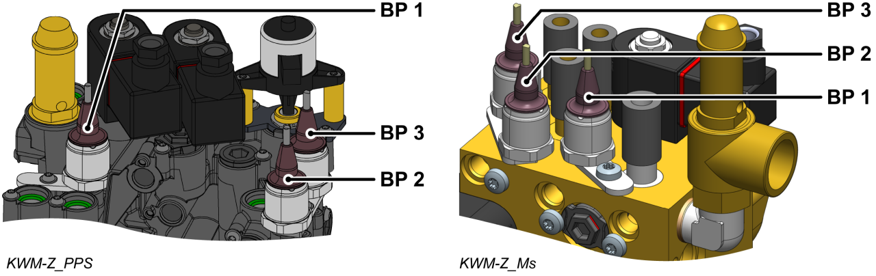
- Remove the pressure sensor cable (BP_1, BP_2, BP_3) on the GIF-61 unit board and completely remove the cable.
- BP 1 → X31.1 (GIF-61)
- BP 2 → X31.2 (GIF-61)
- BP 3 → X31.3 (GIF-61)
- Remove the Torx screw and remove the mounting plate.
- Remove the pressure sensor.
- Use a new O-ring (T28662) if required. Otherwise, use the previous O-ring.
- Make sure the sealing surface is clean and free of debris.
- Install a new pressure sensor and bracket and secure with a mounting screw.
- For plastic cooling water module (PPS), tighten the screw with 2 Nm — do not exceed it!
- Route and connect the cable from the pressure sensor (BP_1, BP_2, BP_3) to the GIF-61 unit board.
- BP 1 → X31.1 (GIF-61)
- BP 2 → X31.2 (GIF-61)
- BP 3 → X31.3 (GIF-61)
- Re-attach removed cable ties or replace them with new ones.
- Fold up the front and secure 2x Torx screws.
Verify calibrating
ATTENTION — danger of incorrect calibrating!
Incorrect calibrating may cause the unit to malfunction. Therefore: check calibrating
- Connect the mains-connector and switch on the main switch (QS 1).
- Make sure the unit is depressurised. The pressure shown by the pressure gauge must be 0.0 (+0.3) bar.
- Select [Display] > [Actual Values] > [System Pressure].
- The system pressure should show 0.0 (±0.1) bar.
- If the deviation is >0.1 bar, the pressure sensor must be calibrated.
Calibrate pressure sensor
In the event of larger linear errors, the individual pressure sensors can be calibrated.
- Select [User Profile] and set it to "Maintenance".
- Select [Service ] > [calibrating ] > [Pressure ] > [Pressure Sensor 1/2/3 Offset].
- Set the offset accordingly.
- Retry the verification process
Check tightness / function
-
Switch on the unit using the I/O button (
 ), check the tightness and function of the unit.
Switch off / install covers
-
Switch off the unit using the I/O button ().
- The unit switches off and, if necessary, is cooled and depressurised.
- Switch off the main switch (QS 1).
- Re-attach covers from the unit (→ Open unit).