PDF
Download PDF
Download page T28494: Touch screen.
T28494: Touch screen
purpose
exchange Touchscreen 7" IPS 180x129 (A 2)
Quallifikaion
Qualified personnel
Material
| Pos. | Designation | article | T28494 |
| 01 | Touchscreen 7" IPS 180x129 | T28494 | 1 |
Required material
- Torx screwdriver size 20
- Flat head screwdriver, size 0
- Hot air blower with temperature control
- Clip-on reducing nozzle (optional, for targeted heating)
- Cleaning/solvent for removing adhesive residues
- protective gloves
procedure
ATTENTION!
Working with the unit requires knowledge of the safety instructions and quick guide. That's why:
Read the safety instructions and quick guide carefully before starting any work. The basic requirement for safe work is compliance with all safety instructions and careful action by qualified qualified personnel to prevent accidents involving personal injury and property damage.
cooling / switch off
- On the basic screen, tap the function button (
 ).
).- The unit cools down until the temperature is lower than the cooling temperature. The unit then switches off.
- Switch off the main switch (QS 1), pull out the mains-connector.
Open front
- Open the front door and fold the front completely down by loosening the two Torx screws.
Replace spare part
- Remove cable cover
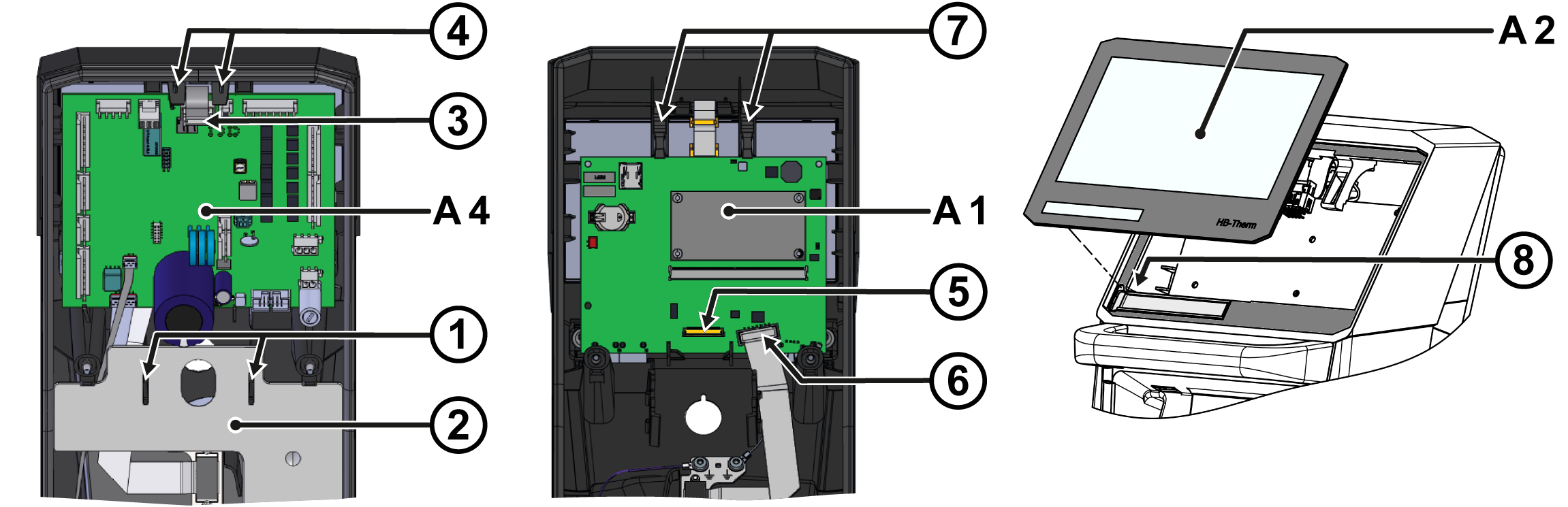
- Squeeze the mounting clips (①) together and remove the cover (②).
- Remove the GIF-61 (A_4) unit board
- Unplug the connector (③) from the circuit board.
- Press the mounting straps (④) outwards.
- Lift out the circuit board and fold it backwards. The remaining connectors on the circuit board do not have to be unplugged.
- Remove USR-61 (A_1) control system
- Unplug the connector (⑤) from the touch screen . Unlock the plug connection before unplugging, for example with a slotted screwdriver.
- Unplug the connector (⑥) from the 'HB' cable on the circuit board.
- Press the mounting straps (⑦) outwards.
- Lift out the circuit board. The remaining connectors on the circuit board do not have to be unplugged.
- Remove the touch screen (A_2)
NOTE!
The temperature during heating must not exceed 100 °C.
- Gently heat the adhesive area by directing the hot air from the outside onto the gap between the touch screen and the front housing.
- Push the touch screen out of the front housing, starting at the top right corner (top view from outside). The adhesive gradually dissolves until the touch screen can be completely removed.
- Installing the touch screen (A_2)
- Remove adhesive residue on the adhesive area of the front housing with a suitable cleaning agent or solvent until it is clean and grease-free.
- Remove the protective film from the adhesive on the back of the new touch screen.
- Use the touch screen carefully and press down firmly on the outer edge/surface. In addition, press down from the back and hold back from the outside.
- Insert the device type name plate into the appropriate slot on the back of the touch screen (⑧).
- Install USR-61 (A_1) control system
- Insert the circuit board into the appropriate recesses. The mounting straps (⑦) must snap into place.
- Re-plug in connectors (⑤, ⑥).
- Install the GIF-61 (A_4) unit board
- Insert the circuit board into the appropriate recesses. The mounting straps (④) must snap into place.
- Plug in the plug connection (③) again.
- Install cable cover
- Insert the cover (②) into the appropriate recesses. The mounting clips (①) must snap into place.
Close front
- Fold up the front and secure 2x Torx screws.
Check function
- Connect the mains-connector and switch on the main switch (QS 1).
-
Switch on the unit using the I/O button (
 ), check the tightness and function of the unit.
Switch off
-
Switch off the unit using the I/O button ().
- The unit switches off and, if necessary, is cooled and depressurised.
- Switch off the main switch (QS 1).