PDF
Download PDF
Download page T28796: GAT-61 control system.
T28796: GAT-61 control system
purpose
Replacing the control system GAT-61 (A 16)
qualification
Qualified electrical personnel
Material
| Pos. | Designation | article | T28796 |
| 01 | control system GAT-61 | T28796 | 1 |
Required material
- Torx screwdriver size 10
procedure
ATTENTION!
Working with the unit requires knowledge of the safety instructions and quick guide. That's why:
Read the safety instructions and quick guide carefully before starting any work. The basic requirement for safe work is compliance with all safety instructions and careful action by qualified qualified personnel to prevent accidents involving personal injury and property damage.
NOTE!
The network settings are stored on the GAT-61 control system and are therefore lost when replaced.
Remove cover

- Cable cover
- Hold down the fastening tabs and lift the cable cover upwards (Fig. → ①).
- Disconnecting connections on the Gate-6
- Disconnect all control cables and the power supply on the Gate-6.
- Housing cover
- Remove the fastening screws (11x) on the back of the Gate-6 (Fig. → ②)
- Press the housing cover together sideways until you hear a click (Fig. → ③). Then remove the cover.
Replace spare part
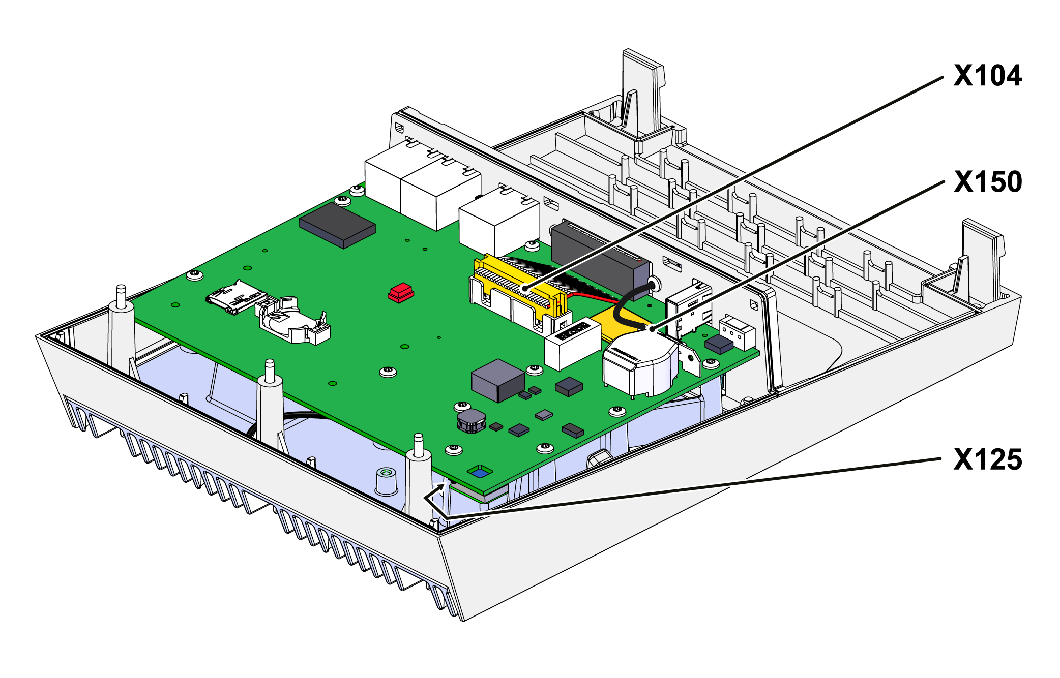
- Detach plug connections on the GAT-61 control system
- 26-pin flat cable → slot X104
- Grounding cable → X150 slot
- Antenna cable (bottom) → X125 slot
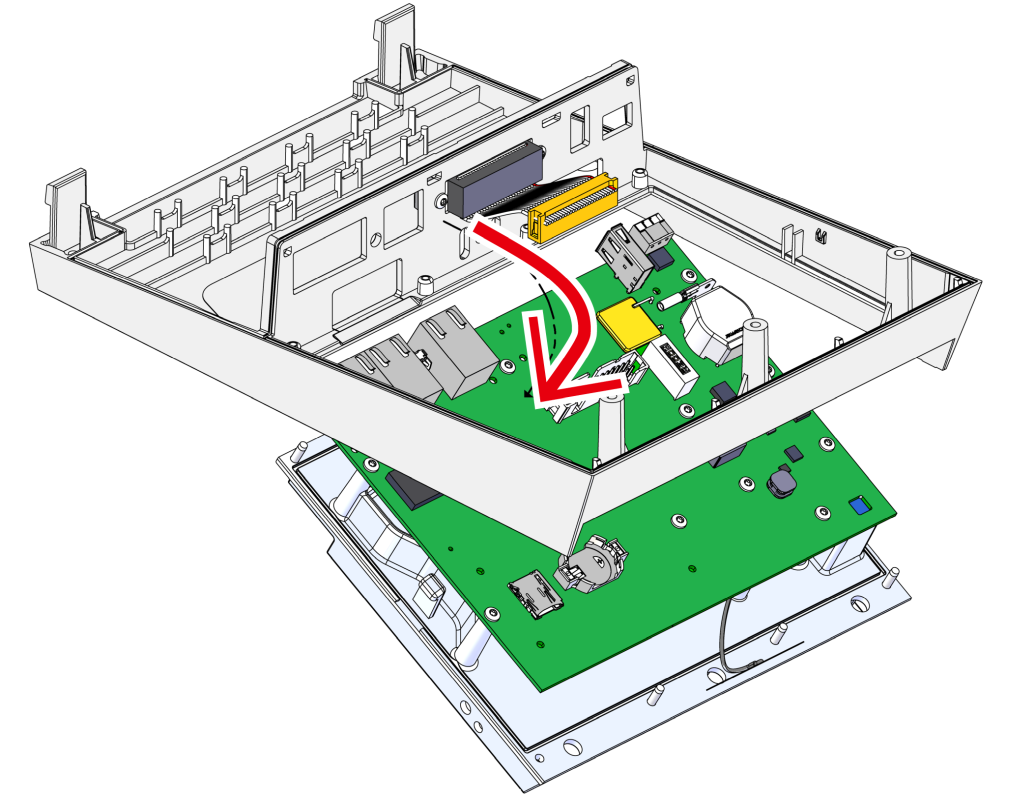
- Remove the GAT-61 control system
- Remove the GAT-61 control system including the heatsink from the housing
- While doing so, push the housing apart to release the mounting straps.
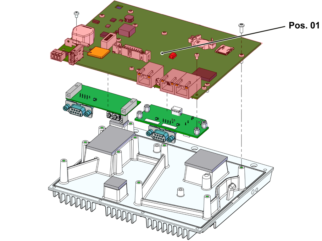
- Remove the GAT-61 control system mounting screws (10x).
- Replace the GAT-61 control system Pos. 01). Transfer additional boards (if available) to the new GAT-61 control system.
- Use GAT-61 control system
- Put the GAT-61 control system back on the heatsink and fix the mounting screws (10x).
- Insert the GAT-61 control system, including the heatsink, into the housing.
- Make sure that the heatsink is locked in place on both sides.
- Restoring plug connections
- 26-pin flat cable → slot X104
- Grounding cable → X150 slot
- Antenna cable (bottom) → X125 slot
Install cover
- Put on the housing cover and press on from above and from the side until you hear a click.
- Attach the fixing screws to the back of the Gate-6.
- Stick the type plate (T19277) on the back of the Gate-6 and in the quick guide (O8406-X).
Check function
- Check communication via the interface in accordance with the procedure in the quick guide.
- Put on the cable cover and press down until you hear a click.