Download PDF
Download page T28822, T2922: temperature sensor.
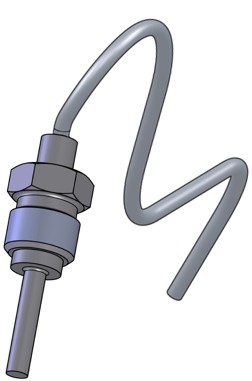
T28822, T2922: temperature sensor
purpose
Replacing the temperature sensor (BT 1, BT 2)
qualification
Qualified personnel
Material
| Pols. | Designation | T28822 | T29322 |
| 01 | temperature sensor Pt 1000, 1,5 m | 1 | - |
| 01 | temperature sensor Pt 1000, 2,05 m | - | 1 |
Required material
- Torx screwdriver size 20
- Torx screwdriver size 10
- open-end wrench, size 10
- Lubricant (prevents stainless-steel combinations from getting stuck)
procedure
ATTENTION!
Working with the unit requires knowledge of the safety instructions and quick guide. That's why:
Read the safety instructions and quick guide carefully before starting any work. The basic requirement for safe work is compliance with all safety instructions and careful action by qualified qualified personnel to prevent accidents involving personal injury and property damage.
Cooling / emptying
- On the basic screen, tap the function button (
 ).
). - On the basic screen, tap the function button (
 ).
).- The unit cools down and evacuation the mold before switching it off.
Check pressure / switch off
- Select [Display] > [Actual Values] > [System Pressure].
- The system pressure must display 0.0 (±0.1) bar.
- The pressure shown by the pressure gauge must be 0.0 (+0.3) bar.
- Switch off the main switch (QS 1), pull out the mains-connector.
Remove covers / open front
Replace spare part
- Remove the temperature sensor cable (BT_1, BT_2) from the GIF-61 unit board and remove the cable tie to completely remove the cable.
- BT 1 → X33.1 (GIF-61)
- BT 2 → X33.2 (GIF-61)
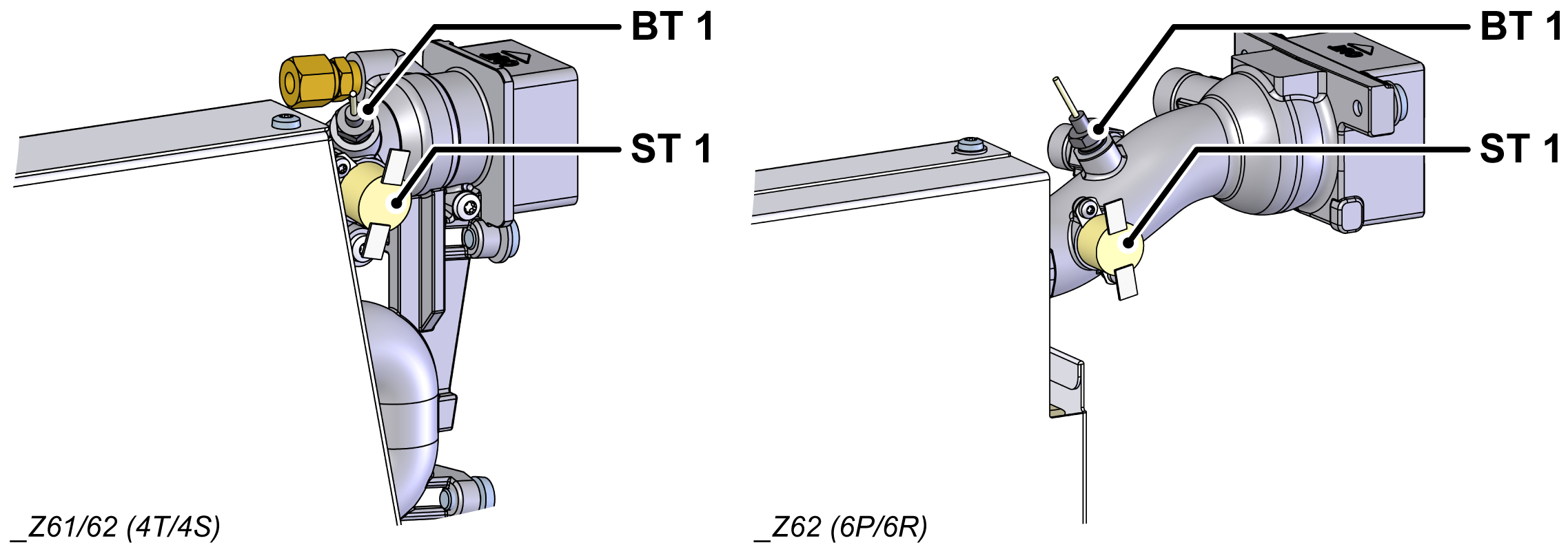
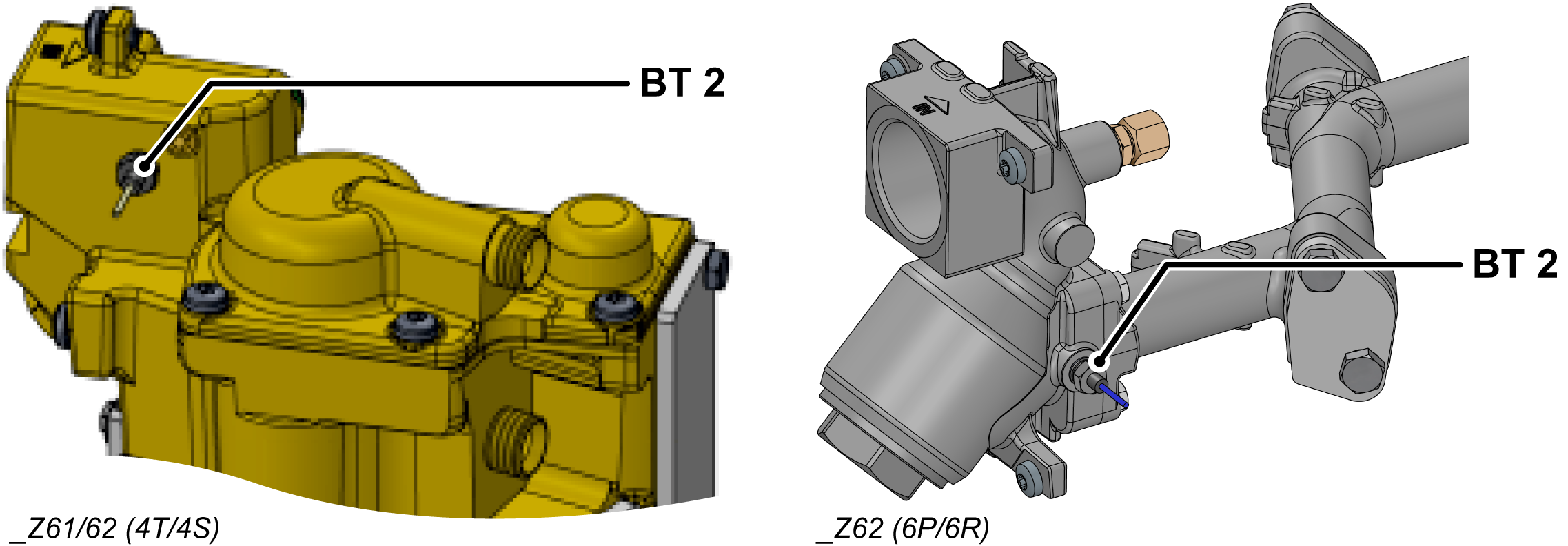
- Remove and remove the temperature sensor (BT_1, BT_2).
- for BT_1: Remove the thermostat (ST_1) to provide access to the temperature sensor.
ATTENTION!
Screw connections, in particular combinations of stainless steel/stainless steel or steel/stainless steel, tend to get stuck or get stuck when operation for a long time at high temperatures. That's why:
Use appropriate lubricants
- Transfer cable lettering from the old temperature sensor to the new one.
- Install a new temperature sensor (BT_1, BT_2) and tighten.
- with BT_1: Install the thermostat (ST_1).
- Make sure the thermostat is firmly attached to the surface.
NOTE!
If the replaced temperature sensor is contaminated, the unreplaced temperature sensor should be cleaned.
- Route and connect the cable from the temperature sensor (BT_1, BT_2) to the GIF-61 unit board.
- BT 1 → X33.1 (GIF-61)
- BT 2 → X33.2 (GIF-61)
- Re-attach removed cable ties or replace them with new ones.
Check tightness / function
- Fold up the front and secure 2x Torx screws.
- Connect the mains-connector and switch on the main switch (QS 1).
-
Switch on the unit using the I/O button (
 ), check the tightness and function of the unit.
ATTENTION — danger of incorrect calibrating!
Incorrect calibrating may cause the unit to malfunction. Therefore: check calibrating
- Calibrate the temperature sensor if necessary. Click here...
Switch off / install covers
-
Switch off the unit using the I/O button ().
- The unit switches off and, if necessary, is cooled and depressurised.
- Switch off the main switch (QS 1).
- Re-attach covers from the unit (→ Open unit).