Download PDF
Download page T28959, T29352, T28960, T29358: Cooling valve 2.
T28959, T29352, T28960, T29358: Cooling valve 2
purpose
Replacing the hydraulic parts of the cooling valve 2 (KV 2)
qualification
Qualified personnel
Material
| Pos. | Designation | article | T28959 | T29352 | T28960 | T29358 |
| 01 | Kolben | T28524 | - | - | 1 | 1 |
| 02 | housing | T29027 | - | 1 | - | 1 |
| 03 | housing | T28847 | 1 | - | 1 | - |
| 04 | Lifting seal 4x10x4.2 (assembled) | T21756 road | 1 | 1 | 1 | 1 |
| 05 | disc 12x2,5 (assembled) | T28865 | 1 | 1 | 1 | 1 |
| 06 | locking ring 13x1 (assembled) | B1255126 | 1 | 1 | 1 | 1 |
| 07 | Cylindrical pin 6x30 (assembled) | B1306553 | 1 | 1 | 1 | 1 |
| 08 | O-ring 24x2 — FPM (optional) | T28658 | - | - | - | - |
Required material
- Torx screwdriver size 20
- open-end wrench, size 10
procedure
ATTENTION!
Working with the unit requires knowledge of the safety instructions and quick guide. That's why:
Read the safety instructions and quick guide carefully before starting any work. The basic requirement for safe work is compliance with all safety instructions and careful action by qualified qualified personnel to prevent accidents involving personal injury and property damage.
Cooling / emptying
- On the basic screen, tap the function button (
 ).
). - On the basic screen, tap the function button (
 ).
).- The unit cools down and evacuation the mold before switching it off.
Check pressure / switch off
- Select [Display] > [Actual Values] > [System Pressure].
- The system pressure must display 0.0 (±0.1) bar.
- The pressure shown by the pressure gauge must be 0.0 (+0.3) bar.
- Switch off the main switch (QS 1), pull out the mains-connector.
Remove cover
- Remove covers from the unit (→ Open unit).
Replace spare part

- Remove the pipe (KV_2 ↔ cooler).
- Pull out the mounting clips
- Remove the pipe on the cooler side first before it can be completely removed
- Remove the cable on the step motor (M_4)
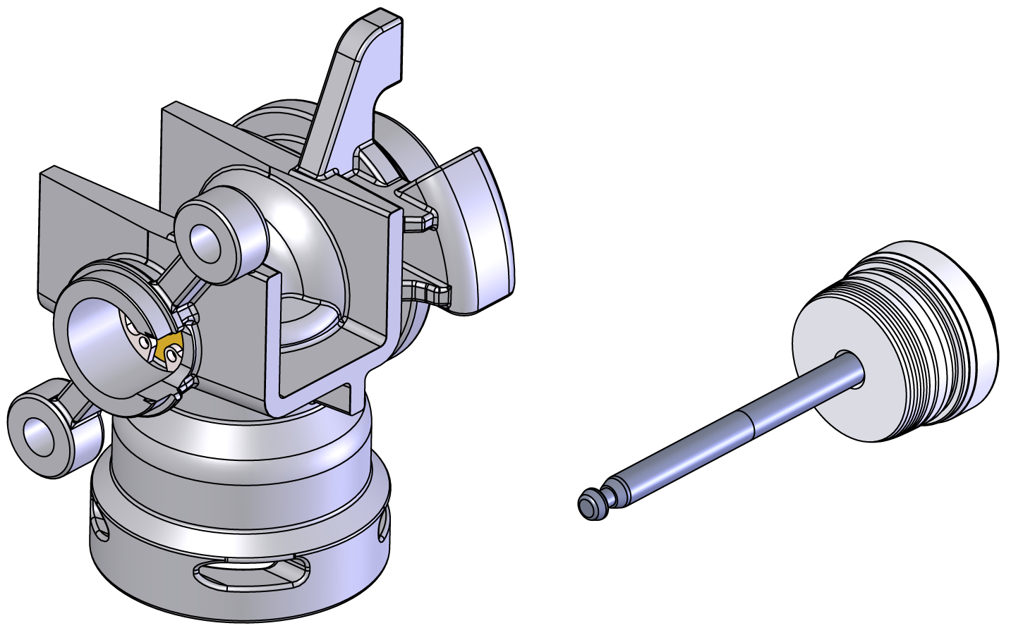
- Remove housing including step motor (M_4) (Fig. → ①).
- Turn the housing until the bayonet lock is released
- Remove the housing completely.
- Remove the step motor (M_4) from the housing (Fig. → ②).
- Remove the mounting screws 2 times
- Turn the step motor, pull it out slightly and move it out of the coupling
- Remove the piston from the housing
- for T28959/ T29352: Clean the piston including rod
- for T28960/T29358: Use a new piston
Leakage due to incorrect installation!
Improper installation of the O-ring may damage it and lead to a leak. That's why:
- Make sure the O-ring is correctly installed.
- Check the housing O-ring for wear and replace if necessary.
- Install the plunger in the new housing (Fig. → ③).
- Insert the plunger carefully and push out the mounting rod
- Remove the mounting rod, this is no longer required.
- Install the step motor (M_4) on the housing (Fig. → ③).
- Drive into the coupling and turn it into the end position
- Fix 2 mounting screws
- Install the pipeline (KV_2 ↔ cooler).
- Check the pipe O-ring for wear and replace if necessary.
- Install the pipeline and secure with mounting clips.
- Connect the cable to the step motor M_4).
Check tightness / function
- Connect the mains-connector and switch on the main switch (QS 1).
- Select [User Profile] and set it to "Maintenance".
- Select [Service] > [Parameter] > [Stepper Motors] > [Positioning KV 2].
- Adjust the value and check whether the step motor including the piston is moving or not:
- 0% = valve closed
- 100% = valve opened
-
Switch on the unit using the I/O button (
 ), check the tightness and function of the unit.
Switch off / install covers
-
Switch off the unit using the I/O button ().
- The unit switches off and, if necessary, is cooled and depressurised.
- Switch off the main switch (QS 1).
- Re-attach covers from the unit (→ Open unit).