Download PDF
Download page T29146: Refurbishment of Flow-5.
T29146: Refurbishment of Flow-5
purpose
Conversion of the flow meter Flow-5
qualification
Qualified personnel
Material
| Pos | Designation | article | T29146 |
| 01 | screw M4x40 Torx - A2 | B3271659 | 2 |
| 02 | screw M4x35 Torx - A2 | B3271658 | 1 |
| 03 | piece of pipe 8x4,5x30 - PEEK | T24717 | 3 |
Required material
- Hexagonal socket screwdriver, size 40
- Torx screwdriver size 15
- Screw locking equipment (e.g. Loctite 620 liquid seal)
procedure
ATTENTION!
Working with the unit requires knowledge of the safety instructions and quick guide. That's why:
Read the safety instructions and quick guide carefully before starting any work. The basic requirement for safe work is compliance with all safety instructions and careful action by qualified qualified personnel to prevent accidents involving personal injury and property damage.
Cool down and drain the unit
(when Flow-5 is installed)
- On the basic screen, tap the function button (
 ).
). - On the basic screen, tap the function button (
 ).
).- The unit cools down and evacuation the mold before switching it off.
Check the pressure and switch off unit
(if Flow-5 is installed)
- Select [Display] > [Actual Values] > [System Pressure].
- The system pressure must display 0.0 (±0.1) bar.
- The pressure shown by the pressure gauge must be 0.0 (+0.3) bar.
- Switch off the main switch (QS 1), pull out the mains-connector.
Remove Flow-5
(if Flow-5 is mounted)
- Remove the control cable from the Flow Meter Flow-5 from the 'HB IN' connection.
- If necessary, remove the connecting lines between the Main line and return lines at all circuits from the flow meter.
- Remove the mounting screw (①) and remove the external flow meter from the temperature control unit.
Refresh Flow-5
NOTE!
The screw connections are secured with adhesive and must therefore be slowly loosened. Otherwise, there is danger that the screw head will break off. If possible, warm up the adhesive compound beforehand.
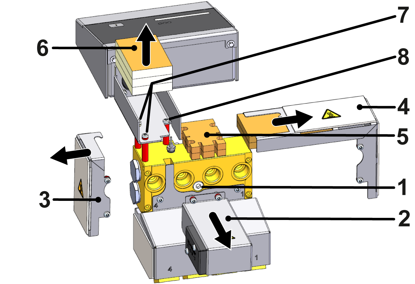
- Remove the cover (②, ③, ④) by removing the Torx screws including the spacer
- Remove insulation (⑤, ⑥).
- Make sure that there is no tensile load on the cable connections.
- Remove Torx screws (⑦, ⑧), including spacers and PEEK tubes (marked in red).
- The evaluation unit must be supported beforehand in such a way that there is no tensile load on the cable connections.
NOTE!
Secure all screw connections with Loctite 620 liquid seal.
- Install two new M4x40 Torx screws (⑦ → B3271659), including the new PEEK pipe pieces (T24717) and the existing spacers.
- Install a new Torx screw (⑧ → B3271658) including the new PEEK pipe piece (T24717).
- Note that no spacer is attached with this screw connector.
- Install the insulation (⑤) between the PEEK pipe pieces (marked in red).
- Insert the insulation (⑥) into the cable duct in such a way that the cable lines are routed between the individual insulations.
- Secure the covers (②, ③, ④) with the Torx screws including the spacer.
- Note that the spacers for the cover (②) are mounted directly under the screw heads.
Check function
- Install the external flow meter to the temperature control unit and tighten the hexagonal socket screw with a maximum torque of 20 Nm.
- If necessary, reinstall the connecting lines between the Main line and the Return line flow at all circuits of the flow meter.
- Connect the mains-connector and switch on the main switch (QS 1).
-
Switch on the unit using the I/O button (
 ), check the tightness and function of the unit.
- Check the plausibility of the display values (flow rate, temperature) of the individual measurement circuits.
Switch off
-
Switch off the unit using the I/O button ().
- The unit switches off and, if necessary, is cooled and depressurised.