Download PDF
Download page T29257: Additional Equipment_ZF.
T29257: Additional Equipment_ZF

Purpose
Retrofitting additional equipment ZF
Qualification
Qualified personnel
Material
| Pos. | Designation | Article | T29257 |
| 01 | Screw connector 6i-1/8 – Ms | T21203 | 1 |
| 02 | Pressure sensor 0–25 bar, 1,4 m – INOX | T25305-6 +T24472-313 | 1 |
| 03 | Flexible tube DN3x570 – Ms | T28636 | 1 |
| 04 | O-ring 7,5x2 – FPM | T28662 | 2 |
| 05 | Screw PT-4x12 – TORX | B3265732 | 1 |
| 06 | Nameplate | T19277 | 3 |
Required material
- Torx screwdriver, size 20, 30
- Open end wrench, size 11
- Cross screwdriver
- Allen wrench, size 5
- Hot air blower
- Liquid seal (e.g. Loctite 620) or Teflon tape
Procedure
ATTENTION!
Working with the unit requires knowledge of the safety instructions and quick guide. That's why:
Read the safety instructions and quick guide carefully before starting any work. The basic requirement for safe work is compliance with all safety instructions and careful action by qualified qualified personnel to prevent accidents involving personal injury and property damage.
Cooling / emptying
- On the basic screen, tap the function button (
 ).
). - On the basic screen, tap the function button (
 ).
).- The unit cools down and evacuation the mold before switching it off.
Check pressure / switch off
- Switch off the main switch (QS 1), pull out the mains-connector.
Remove covers / open front
- Remove covers from the unit (→ Open unit).
- Open the front door and fold the front completely down by loosening the two Torx screws.
- Remove the entire upper air duct cover. To do this, unscrew and remove 6 mounting screws.
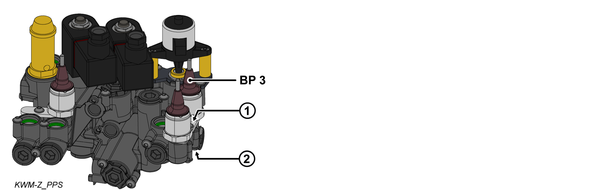
Installing the pressure sensor
- Remove the bracket (①) from the cooling water module.
- Install the O-ring on the pressure sensor (BP_3).
- Install the pressure sensor (BP_3) and bracket and secure them with a mounting screw.
- For plastic cooling water module (PPS), tighten the screw with 2 Nm — do not exceed it!
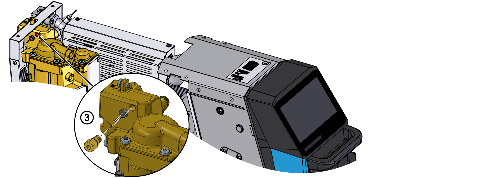
Install hydraulic connection
ATTENTION!
Screw connections are sealed with thread sealant and are therefore slow to release. Otherwise, there is a danger that the screw connection will be damaged (e.g. Tearing off the screw head). That's why:
- If possible, warm up the adhesive compound beforehand
- Remove the screw plug on the heat transfer medium module (WTM).
- Install a new screw connector (③) with thread sealant.
- Install a new DN3 flexible tube between the cooling water module (KWM, ②) and the heat transfer medium module (WTM, ③).
- Re-install the air duct cover with 6x mounting screws.
Connect the cable / Attach the nameplate
- Route and connect the cable from the pressure sensor (BP_3) to the GIF-61 unit board.
- BP_3 → X31.3 (GIF-61)
- Fold up the front and secure 2x Torx screws.
- Place new type plates on the rear wall and on the inside of the front door of the unit.
- Close the front door.
Verify calibrating
ATTENTION — danger of incorrect calibrating!
Incorrect calibrating may cause the unit to malfunction. Therefore: check calibrating
- Connect the mains-connector and switch on the main switch (QS 1).
- Make sure the unit is depressurised. The pressure shown by the pressure gauge must be 0.0 (+0.3) bar.
- Select [Display] > [Actual Values] > [System Pressure].
- The system pressure should show 0.0 (±0.1) bar.
- If the deviation is >0.1 bar, the pressure sensor must be calibrated.
Calibrate pressure sensor
In the event of a larger linear error, the individual pressure sensors can be calibrated.
- Select [User Profile] and set it to “Maintenance”
- Select [Service] > [Calibrating] > [Pressure] > [Pressure sensor 3 Offset].
- Set the offset accordingly.
- Repeat the verification process.
Check tightness / function
-
Switch on the unit using the I/O button (
 ), check the tightness and function of the unit.
Switch off / install covers
Switch off the unit using the I/O button (![]() ).
).
- The unit switches off and, if necessary, is cooled and depressurised.
- Switch off the main switch (QS 1).
- Re-attach covers from the unit (→ Open unit).