Download PDF
Download page Safety instructions / Quick guide Gate-6.
Safety instructions / Quick guide Gate-6
HB-Therm®
Safety instructions and quick guide
Interface Server Gate-6
EN (Translation of original instructions)
General
Read these instructions carefully before starting any work. The basic prerequisites for working safely are compliance with all safety instructions and prudent action by qualified personnel in order to avoid accidents that lead to personal injury / property damage.
Safety instructions are marked by symbols:
Danger! / Warning! / Caution!
![]() ... indicates a hazardous situation which, if disregarded, may result in injury (Caution!) or serious or fatal injury (Warning!, Danger!).
... indicates a hazardous situation which, if disregarded, may result in injury (Caution!) or serious or fatal injury (Warning!, Danger!).
Danger due to magnetic field!
![]() ... if disregarded, there is a risk of material damage or serious injury.
... if disregarded, there is a risk of material damage or serious injury.
Attention!
![]() ... indicates a potentially hazardous situation which, if disregarded, may result in property damage.
... indicates a potentially hazardous situation which, if disregarded, may result in property damage.
Further instruction information is available via the e-cockpit app or http://knowledge.hb-therm.eu, see Section 6. If you have any questions or are unclear, please contact your country representative (see type plate) or our customer service www.hb-therm.com.
Designated use
The Gate-6 is an interface server. The various Series 6 products are connected to the Gate-6 via the standard Euromap 82.1 (Ethernet) interface.
The interface server is able to translate the Euromap 82.1 protocol into various proprietary machine protocols. The required hardware for serial communication (RS-232, RS-485, RS-422 or 20 mA) as well as bus protocols such as CAN or PROFIBUS-DP is optionally available.
One Gate-6 is required per injection moulding machine, which ideally remains firmly connected to the machine. The Gate-6 can communicate with the e-cockpit app via Bluetooth or WiFi.
The Gate-6 is designed and constructed exclusively for the specified values in accordance with its type plate. Claims of any kind due to improper use are excluded.
General safety instructions
![]() Observe the local, legal and company safety regulations and requirements.
Observe the local, legal and company safety regulations and requirements.
![]() Always keep these instructions and all information on the Gate-6 clearly legible. Replace damaged or illegible information immediately.
Always keep these instructions and all information on the Gate-6 clearly legible. Replace damaged or illegible information immediately.
![]() Regularly check the entire system for damage. Remedy any defects immediately.
Regularly check the entire system for damage. Remedy any defects immediately.
![]() Disconnect the Gate-6 from the power supply when opening it to access the control unit.
Disconnect the Gate-6 from the power supply when opening it to access the control unit.
![]() Keep the magnets away from devices and objects that can be damaged by magnetic fields. People with pacemakers must keep a minimum distance of 5 cm from the magnets.
Keep the magnets away from devices and objects that can be damaged by magnetic fields. People with pacemakers must keep a minimum distance of 5 cm from the magnets.
![]() Be mindful of the attractive force between the magnet and the magnetic surface. Disregarding this can lead to bruising in the affected areas.
Be mindful of the attractive force between the magnet and the magnetic surface. Disregarding this can lead to bruising in the affected areas.
![]() Always keep the magnets and the magnetic surface free of contamination to ensure optimum adhesion and avoid damage to the surface.
Always keep the magnets and the magnetic surface free of contamination to ensure optimum adhesion and avoid damage to the surface.
![]() Maintenance work may only be carried out by qualified personnel.
Maintenance work may only be carried out by qualified personnel.
Transport and packaging
Check the delivery immediately on receipt for completeness and for any transport damage.
![]() For careful handling and in-plant transport, observe the symbols and instructions on the packaging.
For careful handling and in-plant transport, observe the symbols and instructions on the packaging.
![]() To protect the Gate-6, do not remove the packaging until shortly before installation.
To protect the Gate-6, do not remove the packaging until shortly before installation.
![]() When shipping a Gate-6, only use the original packaging or equivalent packaging.
When shipping a Gate-6, only use the original packaging or equivalent packaging.
Installation
![]() The electrical installation and initial commissioning must be carried out by qualified personnel.
The electrical installation and initial commissioning must be carried out by qualified personnel.
Installation conditions
| Unit location | water-protected indoor area |
| sufficiently good ventilation (positioning, see figure Section 4.1) | |
| as free-standing as possible (for better Bluetooth reception) | |
| Max. Bluetooth range | 10 m with clear view |
| Max. installation altitude | 3000 m above sea level |
| Installation area Installation | Installation with/without brackets: |
Screw mounting: | |
Magnet mounting: | |
| Max. surface temperature of the installation surface | 40 °C |
| Perm. ambient temperature | 5–40 °C |
| Relative humidity | 35–85 % RH (non-condensing) |
| External cables | Cables must not touch hydraulic lines or parts whose surface temperatures are above 50 °C. |
Connections
![]() The product must be powered by a SELV/LPS power supply (max. power of 6,25 A @24 VDC) with reinforced or double insulation. The power supply must be protected against short circuit and overload.
The product must be powered by a SELV/LPS power supply (max. power of 6,25 A @24 VDC) with reinforced or double insulation. The power supply must be protected against short circuit and overload.
![]() Euromap 82.1 is an open and unprotected protocol. To prevent unauthorised access to units, the Ethernet connection (6) must not be connected to the company network or the internet. If the user interface on the Thermo-6 temperature control unit displays the symbol
Euromap 82.1 is an open and unprotected protocol. To prevent unauthorised access to units, the Ethernet connection (6) must not be connected to the company network or the internet. If the user interface on the Thermo-6 temperature control unit displays the symbol ![]() , there is adirect internet connection.
, there is adirect internet connection.
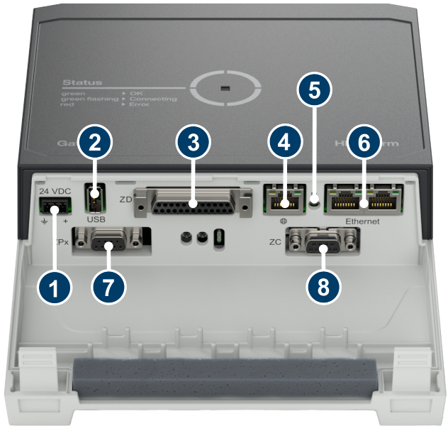
- 24 VDC connection (+ = 24 VDC; – = 0 VDC;
 = Function ground for EMC purposes)
 - USB-A (for service purposes)
- Interface DIGITAL (ZD)
- Ethernet ext. (Internet access)
- Reset button (Reset network settings)
- Ethernet (OPC UA interface for connection of the Thermo-6)
- Interface Profibus-DP (ZP)
- Interface CAN (ZC)
Display/ LED meaning
The standard version of the Gate-6 does not have its own user interface. The settings for the Gate-6 (protocol, e-cockpit coupling, network settings, date/ time) are made via the user interface on the Thermo-6 temperature control unit, which is in the same network as the Gate-6.
![]()
white → Start-up process active
![]()
green → Everything OK. The Gate-6 is connected to at least one Thermo-6 temperature control unit.
![]()
green-flashing → Connection process active. The Gate-6 is establishing a connection with a Thermo-6 temperature control unit.
![]()
blue-flashing → Bluetooth pairing process active
![]()
yellow-red-flashing → Software update active. Note details of the update process on the user interface of the Thermo-6 temperature control unit.
![]()
yellow-flashing → Warning. Note details of the warning on the control panel of the Thermo-6 temperature control unit.
![]()
red-flashing → Fault. Note details of the fault on the control unit of the Thermo-6 temperature control unit.
Commissioning
![]() When putting the Gate-6 into operation for the first time, all electrical connections must be checked.
When putting the Gate-6 into operation for the first time, all electrical connections must be checked.
![]() The Gate-6 is switched on and off by connecting or disconnecting the power supply. All interface cables can be plugged in and unplugged during operation (hot-pluggable).
The Gate-6 is switched on and off by connecting or disconnecting the power supply. All interface cables can be plugged in and unplugged during operation (hot-pluggable).
![]() The HB-Therm units are configured to obtain IP addresses automatically by default (DHCP server available). For the procedure for manual network configuration, see Section 6.
The HB-Therm units are configured to obtain IP addresses automatically by default (DHCP server available). For the procedure for manual network configuration, see Section 6.
Procedure
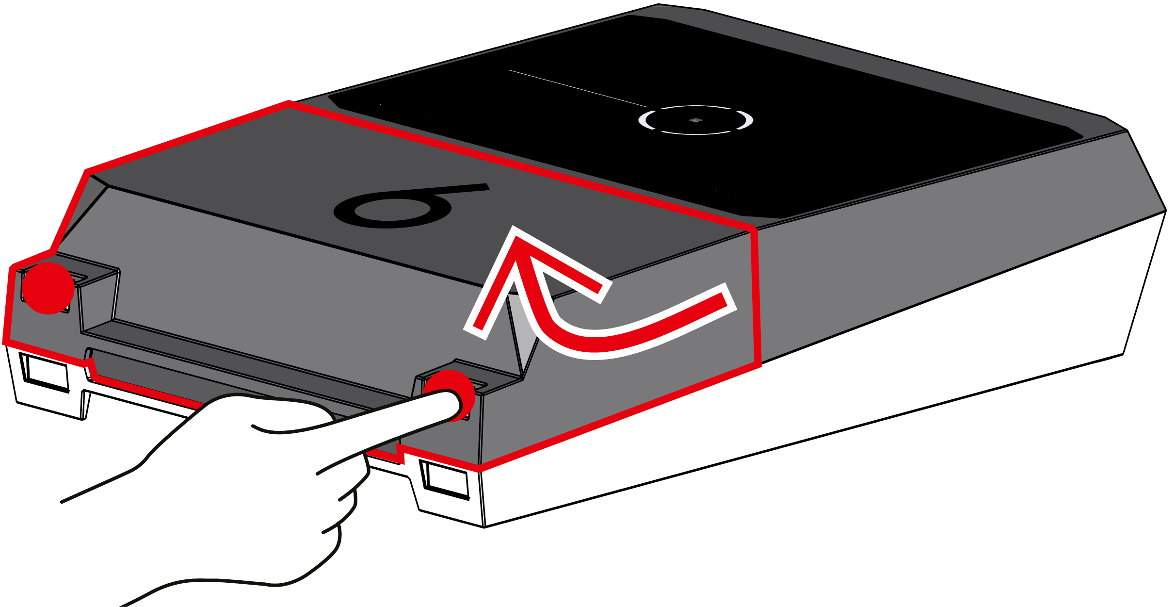
- Hold down both fastening straps and lift the cover upwards.
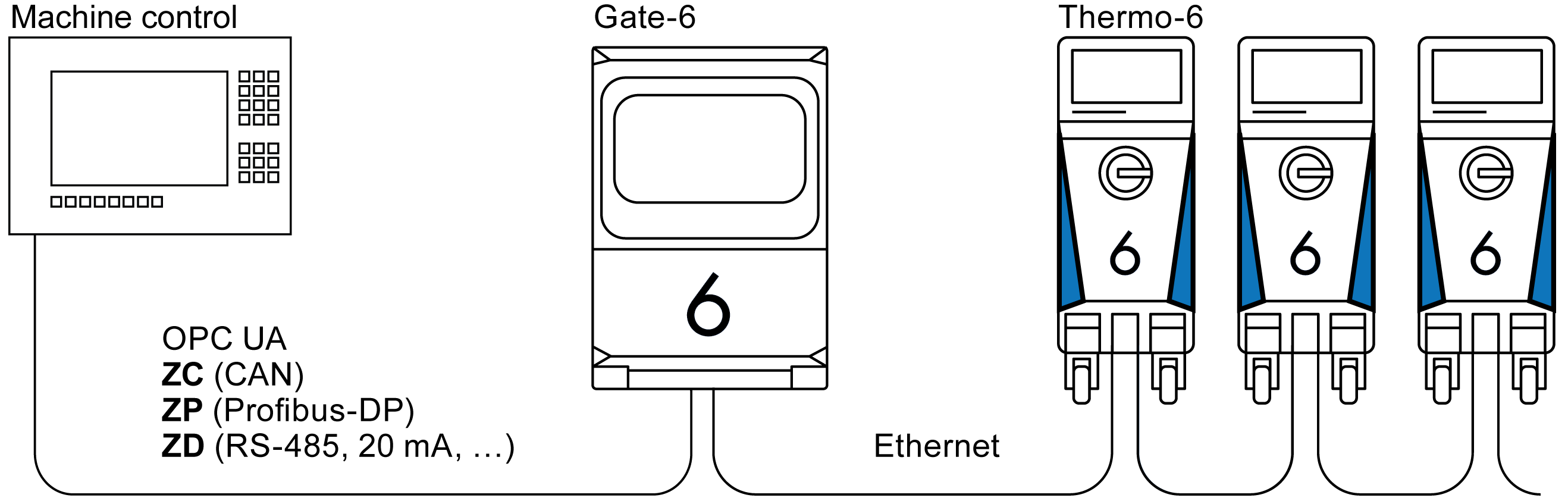
- Connect the control cable as shown in the following picture.

Use shielded cables of category 5 or higher for all Ethernet connections.
- Connect cable for power supply to Gate-6.
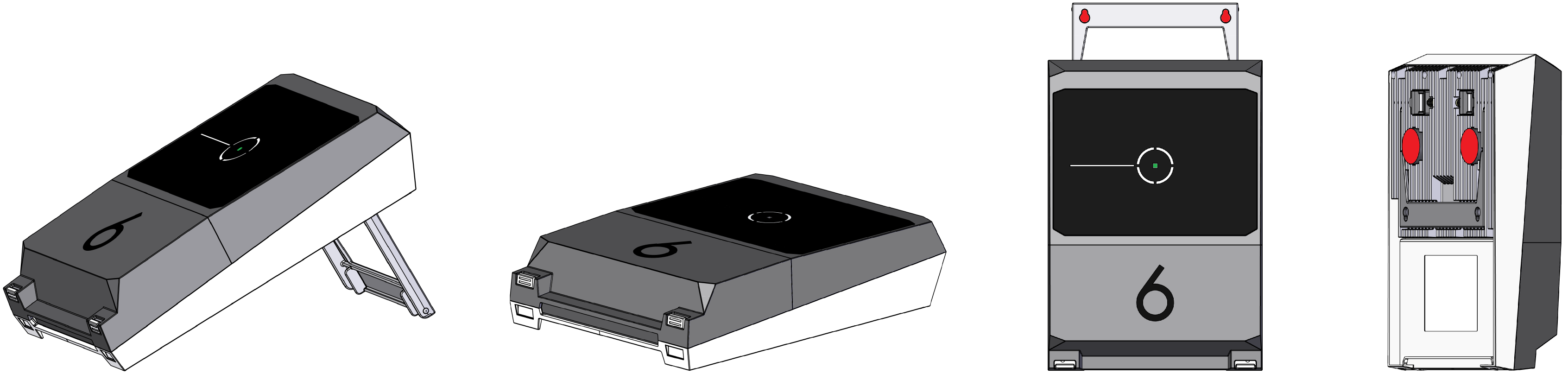
- Position Gate-6 at the desired installation location in one of the possible installation variants (with/without bracket, screw or magnetic mounting).
- Connect the power supply unit to the electrical socket. As soon as the Gate-6 is supplied with voltage, the LED starts to light up white.
→ after initialisation of the unit, the LED flashes green for the duration of establishing the connection (approx. 30 s). If no connection to a Thermo-6 temperature control unit can be established, the LED remains permanently flashing green. In this case, continue with point 6.
→ as soon as the connection to a Thermo-6 temperature control unit has been established, the LED lights up green. Continue with point 7. - Check whether the temperature control units are switched on and correctly connected. If this is the case and it is still not possible to establish a connection, the network settings on the Gate-6 must be reset. To do this, press and hold the reset button on the Gate-6 until the LED flashes white briefly (approx. 3 s).
→ The network settings are reset.
If it is still not possible to establish a connection between the Gate-6 and Thermo-6, check the network setting on Thermo-6 under ʹSettingʹ → ʹRemote controlʹ → ʹNetworkʹ. The Network Configuration parameter must be set to ʺautomaticallyʺ. Exit the Network menu. For further assistance if the connection still cannot be established, see Section 6. - Tap the menu key
 on each connected Thermo-6 temperature control unit → tap ʹSettingʹ → tap ʹRemote control ʹ → tap and set the ʹRemote control addressʹ.
 - Optional only with add-on ZD, ZC, ZP: Set the protocol on a connected Thermo-6 temperature control unit. Tap the menu key on the Thermo-6 temperature control unit→ tap ʹGateʹ → tap ʹProtocol converterʹ → tap and set ʹProtocolʹ.
- Optional only for communication via OPC UA: For communication between the machine control, Gate-6 and Thermo-6 to work, all participants must be in the same network. If a DHCP server is available, the Gate-6 as well as the Thermo-6 must have received an IP address (current) not equal to 169.254.xxx.xxx (the setting can be looked up under ʹSettingʹ → ʹRemote controlʹ → ʹNetworkʹ for the Thermo-6 and under ʹGateʹ → ʹSettingsʹ → ʹNetwork Gate-6ʹ for the Gate-6). If this is the case, communication with the machine control should work. Otherwise, there is no DHCP server and network setting must be done manually. For further assistance, see Section 6.
- Tap the menu button on each connected Thermo-6 temperature control unit → tap ʹFunctionsʹ → switch on ʹRemote control' with slide control (
 ).
).
Using «e-cockpit»
e-cockpit is an app for smartphones and tablets. The data from the Gate-6 and the Thermo-6 temperature control units connected to it are accessed via Bluetooth.
For information on connecting the Gate-6 to the e-cockpit app and its functional options, see Section 6.
Download «HB-Therm e-cockpit» app
![]() HB-Therm accepts no liability for damage caused by the use of the e-cockpit application software downloaded outside of the Google Play Store or App Store.
HB-Therm accepts no liability for damage caused by the use of the e-cockpit application software downloaded outside of the Google Play Store or App Store.
The «HB-Therm e-cockpit» app is available in the Google Play Store or App Store.
Knowledge
Call up the Knowledge home page for general information.
Call up Knowledge directly for detailed help if a connection cannot be established or if the network setting must be made manually.
| Frequency band | WLAN | 2,4 GHz / 5,0GHz | ||
| Bluetooth | 2,4 GHz | |||
| Overvoltage category | I | |||
| Degree of contamination | 2 | |||
| Power supply | 24 VDC ±10 % | |||
The type plate is located on the back of the Gate-6.
The following information can be taken from the type plate:
- Type
- Unit number
- Addition
- Connected values
- Year of manufacture
- Protection class
- Manufacturer
- Service point
- QR code (e-cockpit registration)