Download PDF
Download page T29263-X: Additional Equipment_ZG.
T29263-X: Additional Equipment_ZG
Purpose
Retrofitting additional equipment ZG
Qualification
Qualified personnel
Material
| Pos | Designation | article | T29263-1 | T29263-2 | T29263-3 | T29263-4 |
| 01 | brass module ZGM-X | T29690 | 1 | 1 | 1 | 1 |
| 02 | screw connector 6i-1/8 - Ms | T21203 | 1 | 1 | 1 | 1 |
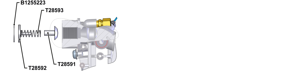
| 03 | cone 19,6x19,5 | T28591 | 1 | 1 | 1 | 1 |
| 04 | Bolt 23,8x19,5 | T28592 | 1 | 1 | 1 | 1 |
| 05 | Compression spring 8,63x0,63x35 - A2 | T28593 | 1 | 1 | 1 | 1 |
| 06 | locking ring 25x1,2 - A4 | B1255223 | 1 | 1 | 1 | 1 |
| 07 | O-ring 7,5x2 - FPM | T28662 | 3 | 3 | 3 | 3 |
| 08 | O-ring 11,9x2,6 - FPM | T23016 | 1 | 1 | 1 | 1 |
| 09 | Torx screw M6x8 - A2 | B3061951 | 1 | 1 | 1 | 1 |
| 10 | flexible tube DN3x570 | T28636 | 1 | 1 | - | - |
| 11 | flexible tube DN8x840 | T29339 road | - | - | 1 | 1 |
| 12 | cable X52.2 1,3 m | T21533-11 | 1 | 1 | - | - |
| 13 | cable X52.2 1,85 m | T21533-8 | - | - | 1 | 1 |
| 14 | seal 29x29x1,5 | T16683 | 2 | 2 | 2 | 2 |
| 15 | cable X52.3, 1,3 m | T29295-1 | 1 | 1 | - | - |
16 | cable X52.3, 1,85 m | T29295-2 | - | - | 1 | 1 |
| 17 | O-ring 17x2 - FPM | T23523 | 1 | - | 1 | - |
| 18 | O-ring 25x2 - FPM | T28709 | 1 | - | 1 | - |
| 19 | Cover 88x41,5x5 | T28964 | 1 | - | 1 | - |
| 20 | screw plug 1/8 - Ms | T15568 | - | 1 | - | 1 |
| 21 | nameplate | T19277 | 3 | 3 | 3 | 3 |
Required material
- Torx screwdriver
- open-end wrench
- Cross screwdriver
- Safety ring pliers
- hot air blower
- Thread sealant (e.g. Loctite 620 liquid seal)
Procedure
ATTENTION!
Working with the unit requires knowledge of the safety instructions and quick guide. That's why:
Read the safety instructions and quick guide carefully before starting any work. The basic requirement for safe work is compliance with all safety instructions and careful action by qualified qualified personnel to prevent accidents involving personal injury and property damage.
Cooling / emptying
- On the basic screen, tap the function button (
 ).
). - On the basic screen, tap the function button (
 ).
).- The unit cools down and evacuation the mold before switching it off.
Check pressure / switch off
- Select [Display] > [Actual Values] > [System Pressure].
- The system pressure must display 0.0 (±0.1) bar.
- The pressure shown by the pressure gauge must be 0.0 (+0.3) bar.
- Switch off the main switch (QS 1), pull out the mains-connector.
Remove connections / covers
ATTENTION!
Screw connections are sealed with thread sealant and are therefore slow to release. Otherwise, there is a danger that the screw connection will be damaged (e.g. Tearing off the screw head). That's why:
- If possible, warm up the adhesive compound beforehand
- Remove all external hydraulic connections on the Main line (OUT) and Return line (IN).
- For units with a serial number up to 2413-nnn: Remove the intermediate adapter.
- Remove covers from the unit (→ Open unit).
- Open the front door and fold the front completely down by loosening the two Torx screws.
- Remove the entire upper air duct cover. To do this, unscrew and remove 6 mounting screws.
Install flexible tube
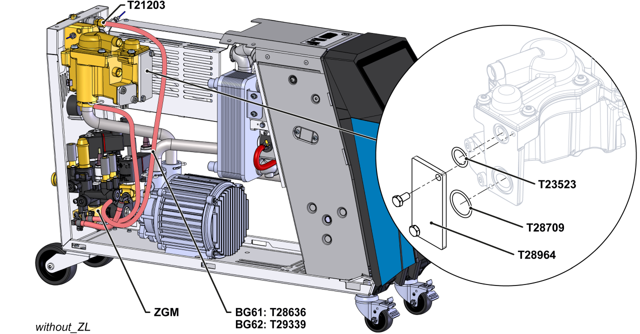
- unit without additional equipment ZL:
- Remove the DN3 flexible tube between the heat transfer medium module (WTM) and the cooling water module (KWM-Z). This line is no longer required.
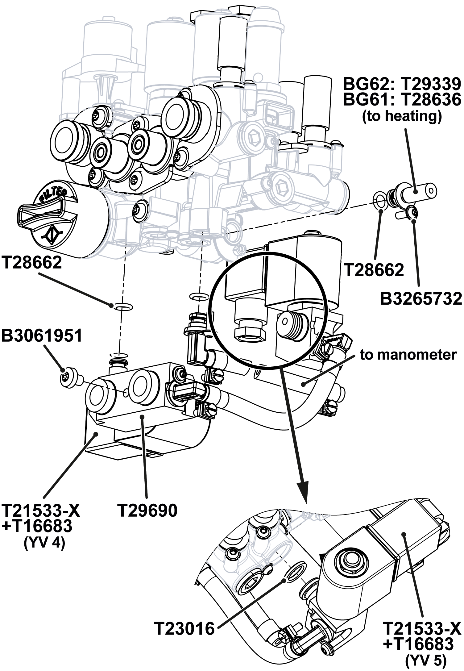
- Replace the cover and O-rings (T28964, T23523, T28709) with existing components on the heat transfer medium module (WTM).
- Remove the screw plug on the heater module (EHM). Install a new screw connector (T21203) with thread sealant.
- unit with additional equipment ZL:
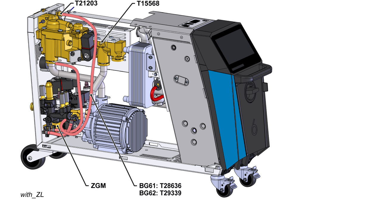
- Remove the DN3 flexible tube between the leak stopper module (ZLM) and the cooling water module (KWM-Z). Line is no longer required
- Remove the screw connector on the leak stopper module (ZLM). Install a new screw plug (T15568) with thread sealant
- Remove the already assembled module (ZLM-1) from the cooling water module. This module is no longer required.
- Install a new DN3 flexible tube between the cooling water module (KWM-Z) and the heater module (EHM).
- HB-100/140/160Z61 → T28636
- HB-100/140/160Z62 (4T/4S) → T29339
- Break out openings (AIR IN, AIR OUT) on the back wall of the unit.
- If necessary: Process perforated areas with a metal chisel and hammer.
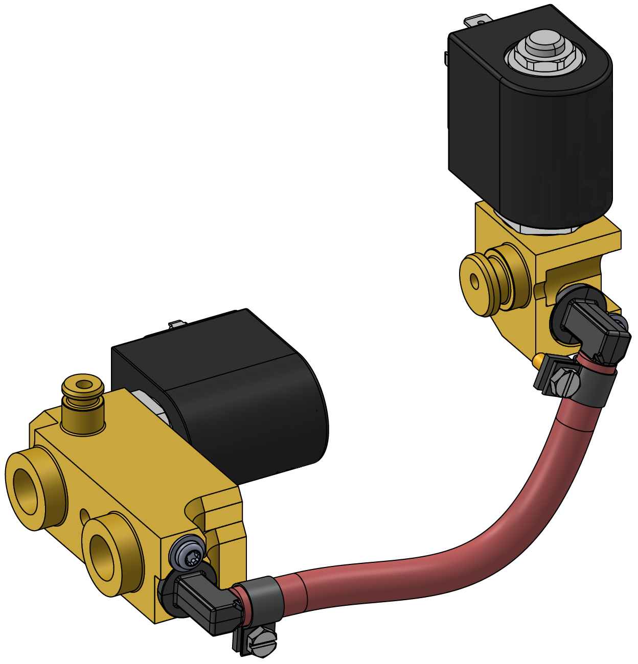
- Install the module (ZGM-X, T29690) with associated components on the cooling water module (KWM-Z) (Fig.).
- Secure the module (ZGM-X) to the rear wall of the device with a screw (B3061951).
Install the non return valve (7.10)
- Install the check valve components at connection A (OUT) and secure them with the locking ring (fig.).
- Re-install the air duct cover. Secure with 6 mounting screws.
Connect the cable / Attach the nameplate
- Route the valve cable (T29295-X, T21533-X) along the existing cable harness into the electrical housing.
- Connect the valve cable to the unit board (GIF-61):
- YV 4 (T21533-X) → X52.2 (GIF-61)
- YV 5 (T29295-X) → X52.3 (GIF-61)
- Replace removed cable ties with new ones.
- Fold up the front and secure 2x Torx screws.
- Stick on the nameplate (T19277):
- on the back wall of the unit
- on the inside of the front door
- in the quick guide (O8402-X)
Check tightness / function
- Re-install external hydraulic connections on the Main line (OUT) and Return line (IN).
- Connect the compressed air supply (AIR_IN connection).
- Connect the cooling water supply (connection C).
- Connect the mains-connector and switch on the main switch (QS 1).
-
Switch on the unit using the I/O button (
 ), check the tightness and function of the unit.
Switch off / install covers
-
Switch off the unit using the I/O button ().
- The unit switches off and, if necessary, is cooled and depressurised.
- Switch off the main switch (QS 1).
- Re-attach covers from the unit (→ Open unit).