Download PDF
Download page T29745-X: Additional Equipment_ZN.
T29745-X: Additional Equipment_ZN
purpose
Retrofitting additional equipment ZN
qualification
Qualified personnel
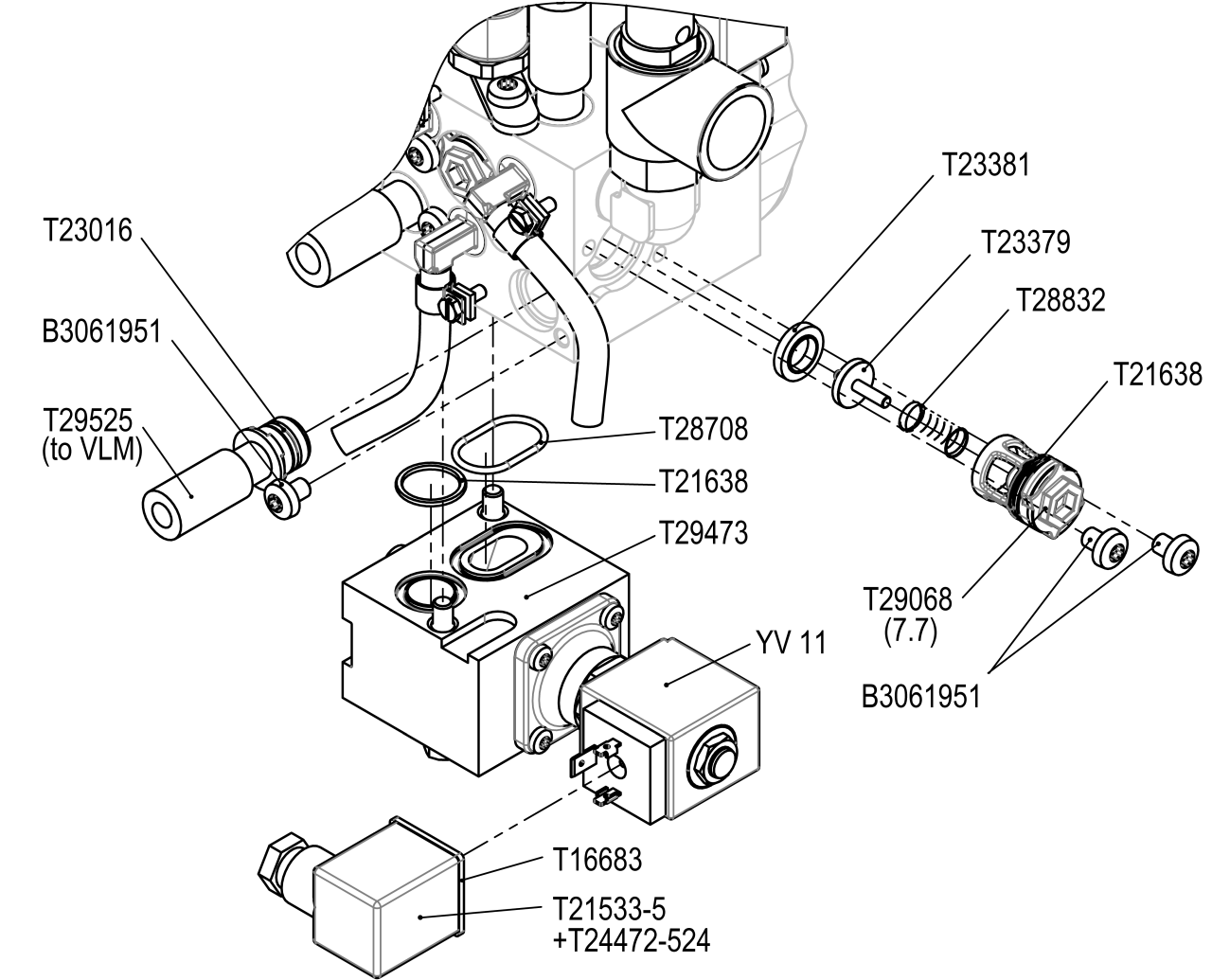
Material
| Pos. | Designation | article | T29745-1 | T29745-2 |
| 01 | brass module ZNM | T29473 | 1 | 1 |
| 02 | O-ring 17x2 - FPM | T21638 | 2 | 2 |
| 03 | O-ring 25x2 - FPM | T28708 | 1 | 1 |
| 04 | seal 29x29x1,5 | T16683 | 1 | 1 |
| 05 | cable X52.4 (YV 5) | T21533-5 | 1 | 1 |
| 06 | pressure piece 26x29 - PPS | T29068 | 1 | 1 |
| 07 | seal FPM | T23381 | 1 | 1 |
| 08 | Compression spring 10,2x0,7x23,75 | T28832 | 1 | 1 |
| 09 | Flap to valve | T23379 | 1 | 1 |
| 10 | flexible tube DN10x600 | T29525 | 1 | 1 |
| 11 | O-ring 11,91x2,62 - FPM | T23016 | 1 | 1 |
| 12 | Torx screw M6x8 | B3061951 | 3 | 3 |
| 13 | stainless steel module VLM | T29444 road | 1 | 1 |
| 14 | seal 35x38x1 - PTFE | T29506 | 1 | 1 |
| 15 | stainless steel module VLM 160 °C (AV_1) | T29442-1 | 1 | - |
| 16 | stainless steel module VLM 180 °C (AV_1) | T29442-2 | - | 1 |
| 17 | hexagonal screw M6x18 | T29509 | 4 | 4 |
| 18 | cable X32.3 (M 9) | T23778-11 | 1 | 1 |
| 19 | cable tie | T14121 | 6 | 6 |
| 20 | nameplate | T19277 | 3 | 3 |
Required material
- Torx screwdriver
- Open-end wrench
- Cross screwdriver
- Allen wrench
- Hot air blower
procedure
ATTENTION!
Working with the unit requires knowledge of the safety instructions and quick guide. That's why:
Read the safety instructions and quick guide carefully before starting any work. The basic requirement for safe work is compliance with all safety instructions and careful action by qualified qualified personnel to prevent accidents involving personal injury and property damage.
Cooling / emptying
- On the basic screen, tap the function button (
 ).
).- The unit cools down until the temperature is lower than the cooling temperature. The unit then switches off.
- Slowly loosen the screw plug at the connection, drain (G) until the unit is depressurised. This prevents liquid splashes.
- Place the collection container under the connection.
- Remove screw plug and allow the medium to drain off.
- After completely drain, reinstall the screw plug.
Switch off / remove connections
- Switch off the main switch (QS 1), pull out the mains-connector.
- Remove the cooling water supply (connection C).
- Remove all external hydraulic connections at the Main line (OUT) and Return line (IN)
- For units with a serial number up to 2413-nnn: Remove the intermediate adapter
Remove covers / open front
- Remove covers from the unit (→ Open unit).
- Open the front door and fold the front completely down by loosening the two Torx screws.
- Remove the entire upper air duct cover. To do this, unscrew and remove 6 mounting screws.
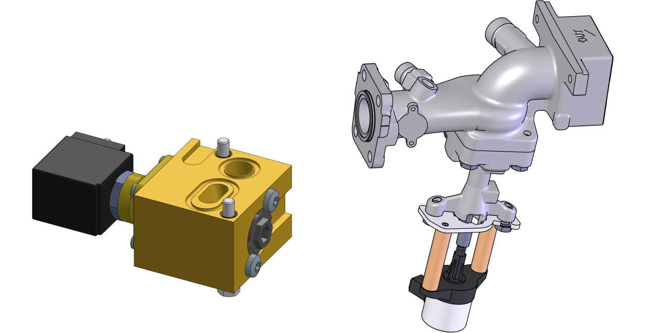
Install brass module (ZNM)
ATTENTION!
Screw connections are sealed with thread sealant and are therefore slow to release. Otherwise, there is a danger that the screw connection will be damaged (e.g. Tearing off the screw head). That's why:
- If possible, warm up the adhesive compound beforehand
- Disassemble the cooling water module (KWM-Z) and set aside.
- Remove two plug screws on the underside of the cooling water module, as shown.
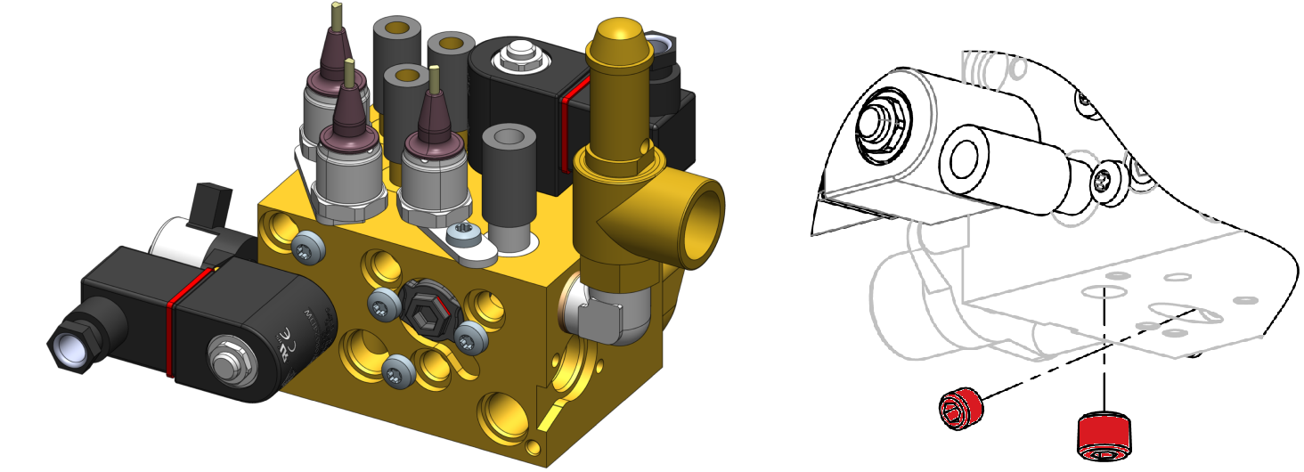
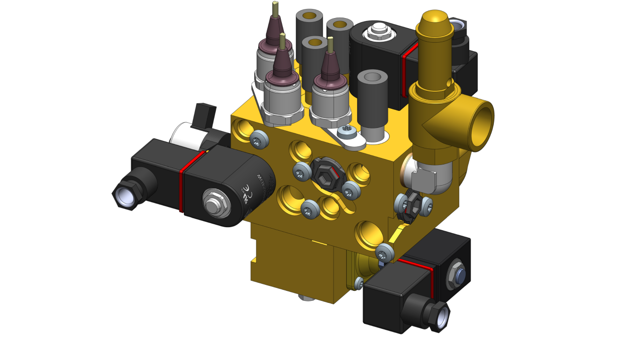
- Install the brass module (ZNM, T29473) including associated components as shown on the underside of the cooling water module (KWM-Z).
- Reinstall and install the cooling water module (KWM-Z).
Install stainless steel module (VLM, AV_1)
- Remove the heater module (EHM) and put it aside.
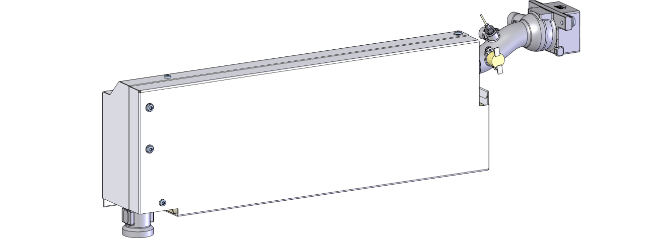
- Remove the stainless steel module (VLM) that has already been installed on the heater module (EHM). This module is no longer required.
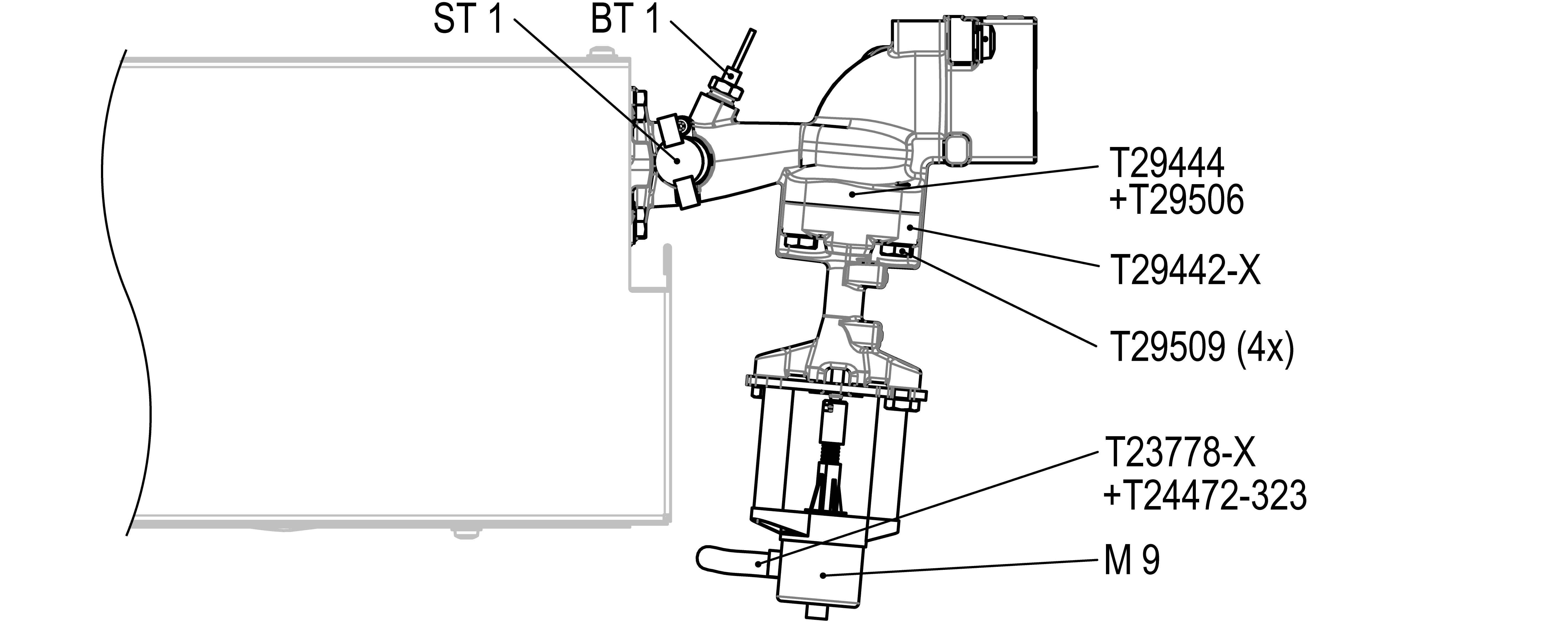
- Install the stainless steel module (VLM, T29442-X, T29444) including associated components on the heater module (EHM) as shown.
- Transfer the temperature sensor (BT_1), thermostat (ST_1) and flexible tube connection (bypass) to the new stainless steel module.
- Reinstall and install the heater module (EHM).
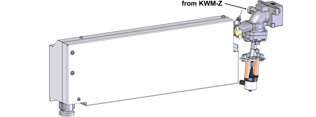
- Connect the DN10 flexible tube (T29525) from the cooling water module (KWM-Z) to the stainless steel module (VLM) and tighten.
- Re-install the air duct cover with 6x mounting screws.
Connect the cable / Attach the nameplate
- Route the valve cable (T21533-5, T23778-11) along the existing cable harness into the electrical housing.
- Connect the valve cable to the unit board (GIF-61):
- YV 11 (T21533-5) → X52.4 (GIF-61)
- M 9 (T23778-11) → X32.2 (GIF-61)
- Replace removed cable ties with new ones.
- Fold up the front and secure 2x Torx screws.
- Stick on the nameplate (T19277):
- on the back wall of the unit
- on the inside of the front door
- in the quick guide (O8402-X)
Check tightness / function
- Re-install external hydraulic connections on the Main line (OUT) and Return line (IN)
- Connect the cooling water supply (connection C).
- Connect the mains-connector and switch on the main switch (QS 1).
-
Switch on the unit using the I/O button (
 ), check the tightness and function of the unit.
Switch off / install covers
-
Switch off the unit using the I/O button ().
- The unit switches off and, if necessary, is cooled and depressurised.
- Switch off the main switch (QS 1).
- Re-attach covers from the unit (→ Open unit).