Download PDF
Download page Connect the Flow meter Flow-5.
Connect the Flow meter Flow-5
Installation
To display and monitor measured values from the Flow meter Flow-5 on a Thermo-6, connect the HB control cable to the Thermo-6 temperature control unit.
NOTE!
Unit software requirement
The software SW61-1_2247 or higher on the Thermo-6 is required to operation the Flow-5 flow meter on the Thermo-6 temperature control unit.
- Provide the Thermo-6 temperature control unit.
- Install the Flow meter Flow-5 on the temperature control unit.
→ The hydraulic connection can be found in the Flow-5 (O8295-DE) flow meter instructions. - Open the door on the front of the temperature control unit.
- Plug control cable HB into socket HB (X 79).
→ The cable layout of the HB control cable can be seen on the following page data interfaces - Connect the other side of the control cable to the HB IN socket on the Flow meter Flow-5.
- Connect additional Flow meter Flow-5 via the HB OUT socket.
NOTE!
When a Flow meter Flow-5 is detected, the software version between the flow meter and the Thermo-6 temperature control unit is checked. If they do not have the same version, the Flow meter Flow-5 is automatically updated to compatible firmware.
Setting up new Flow meter Flow-5
New flow meter detected
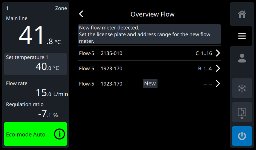
The "Flow" overview window on the Thermo-6 temperature control unit opens automatically as soon as a new flow meter is connected. For the flow meter to function correctly, the labelling (A..D) and the address range () must be set (tap the ">" control icon on the newly recognized flow meter 1..4, 5..8, ...). Unassigned flow meter are shown with “-- --”.
Assignment
NOTE!
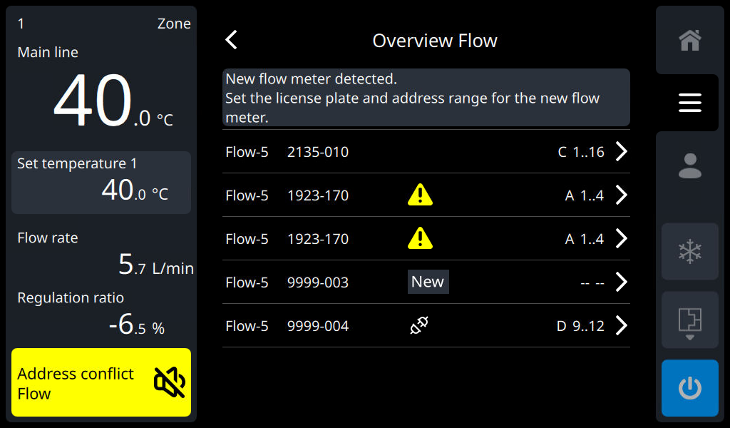
The address range (A..D) can only be assigned to an identifier (1..4, 5..8, ...) once. In the case of multiple assignments, this is signaled with an assignment conflict.
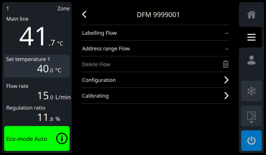
| Labelling Flow | The Flow meter Flow-5 must be assigned a label (A..D) |
| Address range Flow | The measurement circuits of the Flow meter Flow-5 must be assigned to an address range (1..4, 5..8, ...). With the Flow meter Flow-5 (model: autonomic assembly), the address range is automatically assigned. |
Status options in the Flow overview window
The overview shows all flow meter with device No., status, labelling (A..D) and address range (1..4, 5..8, ...). The following status options are available:
| Flow meter connected to the temperature control unit, assignment is missing (re-registered or assignment removed). For the flow meter to function correctly, the labelling (A..D) and the address range (1..4, 5..8, ...) must be set. |
No symbol | Connected flow meter with assignment (registered). The flow meter is ready to use. No action is required. |
| The flow meter is known to the temperature control unit, but not currently connected to the temperature control unit. If this flow meter is available, check the wiring. |
| Assignment conflict for the marked flow meters (same labelling and same address range). The assignment conflict must be resolved by adjusting the labelling (A..D) or the address range (1..4, 5..8, ...). |
Command
Flow meter display
Main menu
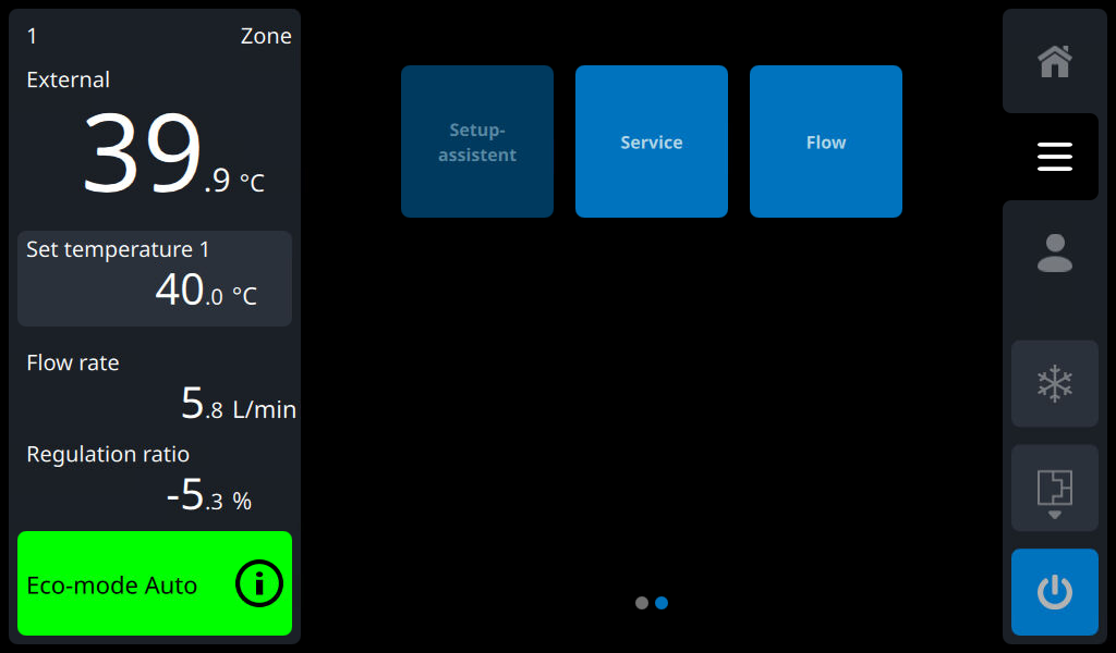
The "Flow" tile is displayed in the main menu, regardless of whether a Flow meter Flow-5 is connected or not.
Submenu

Once the Flow meter Flow-5 has been assigned, it act also listed in the "Flow" submenu (Flow A, Flow B, Flow C, ..).
Actual value display
Each connected flow meter with assignment (A 1..4, B 1..8, ...) extends the standard display with 2 screen pages (indicator graph and list form). The screen pages can be accessed via the register symbols or by swiping through the content of the main screen.
NOTE!
The arrow symbol (“<” or “>”) in the tab bar indicates more tab symbols on the next page. These can be displayed by swiping left or right in the area of the register symbols or by tapping on the arrow symbol (” <” or “>”).
The 2 screen sides of the flow meter are shown with the following symbols. Depending on the labelling set, the symbol is supplemented with "Flow A”, "Flow B", etc.
This allows easy and clear access to the actual values of the respective flow meter.
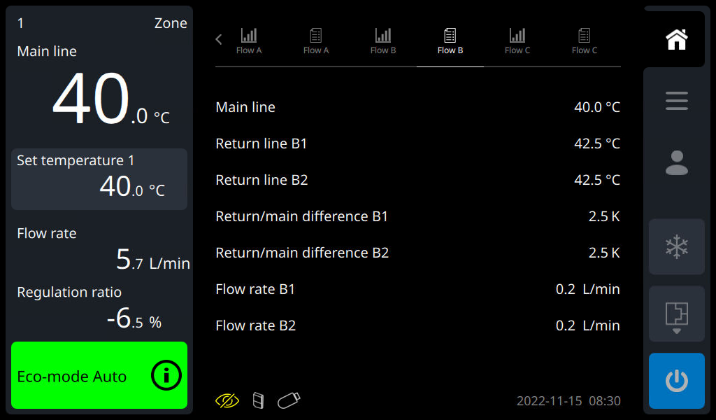
| Actual value display in list form The actual values of the measurement circuits are displayed in the form of a list. The selection of favourites is currently not available. |
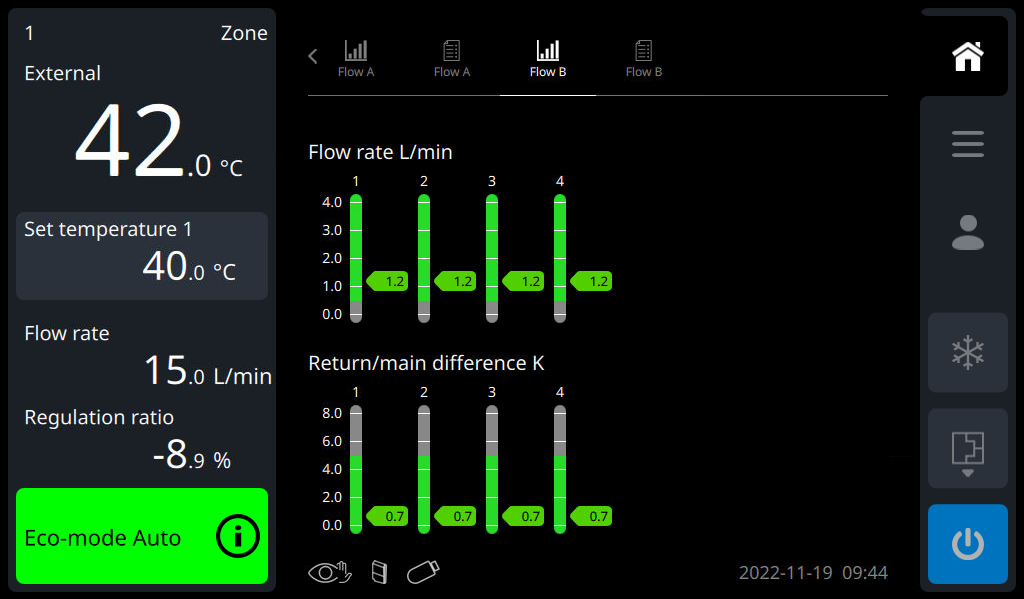
| Actual value display as an indicator graph The actual values flow rate and difference between Main line and Return line from the measuring circuit are displayed graphically as indicators. In addition, the set limit values and set values are displayed. |
Overview Flow
The overview shows all flow meter with device No., status, labelling (A..D) and address range (1..4, 5..8, ...). The following status options are available:
| Flow meter connected to the temperature control unit, assignment is missing (re-registered or assignment removed). For the flow meter to function correctly, the labelling (A..D) and the address range (1..4, 5..8, ...) must be set. |
No symbol | Connected flow meter with assignment (registered). The flow meter is ready to use. No action is required. |
| The flow meter is known to the temperature control unit, but not currently connected to the temperature control unit. If this flow meter is available, check the wiring. |
| Assignment conflict for the marked flow meters (same labelling and same address range). The assignment conflict must be resolved by adjusting the labelling (A..D) or the address range (1..4, 5..8, ...). |
Flow meter Flow-5 status of the unit
NOTE!
Depending on the operating mode, the status indicators of the flow meter or the individual circuits blink in other different colors or sequences. The definitions of the conditions can be found in the Flow-5 (O8295-DE) flow meter instructions.
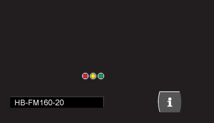
model: unit attachment (with info button + 3 status LED)
NOTE!
The Flow-5 Flow meter Flow-5 (model: unit attachment) have an information button. By pressing the info button, the default display on the Thermo-6 temperature control unit changes to the flow meter graph indicator. This makes it easy and quick to display the important process values from the flow meter on the temperature control unit.
Importance of the different color conditions on the Flow meter Flow-5 (model: unit attachment).
| blinking green-yellow (fast) | New flow meter detected. The flow meter must still be set up (assigned) on the temperature control unit. |
| blinking green (fast ) | The flow meter submenu ([Flow] > [Flow A, Flow B, ..] > [Settings] > [DFM_Serial-No.]) is selected on the Thermo-6 temperature control unit. |
model: autonomic assembly (with status light per measuring circuit)
With the selected flow meter in the standard display, all status indicators of the associated circuits blink green (fast).
| blinking green (fast ) | The flow meter submenu ([Flow] > [Flow A, Flow B, ..] > [Settings] > [DFM_Serial-No.]) is selected on the Thermo-6 temperature control unit. |
Settings
Change Assignment
If an error was made during an assignment (labelling or address range) with a flow meter or the assignment is no longer correct for other reasons, it can also be changed retroactively at any time.
- Select [DFM_Serial-No.] > [Flow A, Flow B, ...] > [Settings ] > [DFM_Serial-No.]
- Set the labelling and address range again.
NOTE!
The status of the unit of the selected Flow-5 flowmeter flashes green (fast).
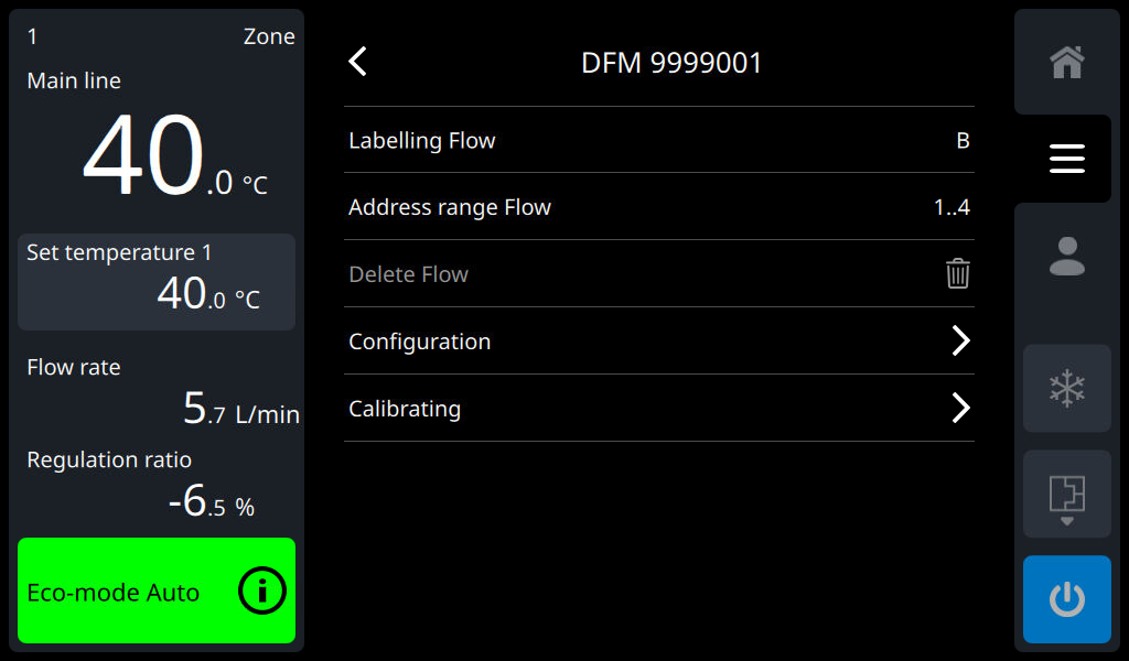
Delete flow meter from overview
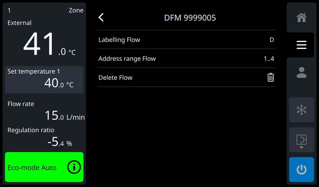
The flow meter overview shows all flow meters that have flow meter identified once on the temperature control unit, regardless of whether they are currently connected to the temperature control unit or not. If a Flow meter Flow-5 is no longer required on a temperature control unit, it can be deleted from the memory of the Thermo-6 temperature control unit. Deleting is only possible when the Flow meter Flow-5 is not connected.
- Select [Flow] > [Flow A, Flow B, ...] > [Settings ] > [DFM_Serial-No.]
- By tapping on the symbol (
 ), the respective flow meter is deleted.
→ The labelling, the address range and all monitoring settings are deleted
NOTE!
A deleted Flow meter Flow-5 can be re-registered and assigned at any time by connecting it to the Thermo-6 temperature control unit.
Activate and deactivate measurement circuits

Individual measuring circuits of the Flow meter Flow-5 can be activated or deactivated depending on the application.
- Select [Flow] > [Flow A, Flow B, ...] > [Measuring Circuit Active]
- Activate or deactivate the measurement circuits with the slider (
 ,
,  ).
).
NOTE!
When measurement circuits are deactivated (slider switched off), no actual values are displayed, no limit values are monitored and no alarms (e.g. Sensor failure) are emitted.
Process monitoring

In the standard setting, the limit values for process monitoring are automatically determined and set after each device is started, in accordance with the selected monitoring level. If automatic limit value determination is not desired, it can be set to manual setting or switched off. See the description on the following page → Monitoring.
If the monitoring type act set to manual, the temperature or flow rate limit value can be set separately for each measuring circuit of the Flow meter Flow-5, or the monitoring can be switched on or off separately.
- Select [Flow] > [Flow A, Flow B, ...] > [Monitoring ] > [Temperature or Flow Rate]
- Switch on monitoring on or off with the slider (
 , )
, ) - Set the temperature or flow rate limit value to the desired value
The selected monitoring type (automatically, manual, OFF) and the set monitoring level (fine, middle, rough) apply to both the Thermo-6 temperature control unit and the Flow-5 Flow meter Flow-5. A separate setting is not possible.
Operating mode
Remote control
In order to transfer the measurement values of the Flow-5 flow meter to an external controller, the following Interfaces are available for a connection between the Thermo-6 temperature control unit and the machine control system.
- Ethernet interface OPC UA(EUROMAP 82.1 Release 1.01 / OPC 40082-1) → Thermo-6 interfaces
- Serial interface DIGITALDIGITAL (ZD) → Gate-6 interface
The following measurement values can be transferred from the machine upon request. Which measurement values are requested from the machine depends on the transmission protocol used and the software version of the machine.
- Flow rate per measuring circuit
- main line temperature per flow meter Flow-5
- return line temperature per measuring circuit
- Temperature difference return/flow per measuring circuit
To be able to communicate with the external control system via the Interfaces, see the description on the following page → Remote control
Special feature of the Interface DIGITAL
Advanced interface protocol
In order for the measured values to be transferred from the flow meter to the machine via the serial interface, the corresponding protocol 1, 4 or 5 must also be extended on the machine side.
NOTE!
The hardware and software required for the machine control system must be clarified with the machine manufacturer.
The following machine manufacturers are known to have implemented an extension:
| Manufacturer | Protocol | Measured value display |
|---|---|---|
Arburg | 1 |
|
Sumitomo Demag | 1 |
|
Simulate flow meter as a device
If this function act switched on, each measuring circuit is assigned an address by the external flow meter for communication with the machine. The Simulate Flow as a unit function enables the transfer of flow values from external measurement circuits to machine controls that neither support the extended interface protocol 1, 4 and 5 nor the OPC UA Euromap 82.1 Ethernet interface (EUROMAP 82.1 Release 1.01 / OPC 40082-1). This allows the flow values of the external flow meter Flow-5 to be transferred to the injection moulding machine without changing the software.
NOTE!
Prerequisite:
- Software SW61-1_2306 or higher → Unit software
- DIGITAL (ZD ) serial interface, protocol 1, 4 or 5 → Gate-6 interfaces
- Machine control supports the required number of device addresses (e.g. For a Thermo-6 with a flow with 4 measurement circuits, 4 unit addresses must be supported by the machine control!)
- Select [Setting] > [Remote Control] > [Simulate Flow as a unit] (→ only available if a flow meter (Flow) is also connected)
- Use the slider (, ) to turn the function on or off.
→ A simulated unit address is automatically assigned to each measuring circuit.
→ Inactive measurement circuits also receive an address assignment.
The address set on the Thermo-6 temperature control unit is used as the starting point for address assignment. The address range used is displayed in the address field of the temperature control unit (e.g. “3..6” if the address “3" is set to the temperature control unit and a flow with 4 measuring circuits is connected). If the following addresses have already been assigned elsewhere from the starting point, this will be notified by a warning. An address (starting point) with a subsequent free address range is required for the number of measurement circuits.
NOTE!
It is not possible to manually and individually assign addresses to the simulated device addresses for the measurement circuits.
Check the Flow rate measurement
Qualification
- Qualified personnel
Equipment needed
- Hydraulic lines between Main line and Return line with shut-off valve on all measuring circuits
Procedure
- Switch on the unit with an external flow meter Flow-5.
- Select [Set Values] > [Set Temperature ]
→ Set the parameter to 40 °C. - Select [Flow] > [Flow n] > [Actual Values]
- Close all shut-off valves between Main line and the Return line.
→ The [Flow rate A1..D16] parameter must display 0.0 L/min.
Calibrate Flow rate measurement
If there is a deviation, the Flow rate measurement must be calibrated.
NOTE!
Calibrating must be carried out with pure water (without additives).

- Switch on the unit with an external flow meter Flow-5.
- Select [Set Values > [Set Temperature].
→ Set the parameter to 40 °C. - Select [Setting] > [Miscellaneous] > [Pressure relief at shutdown].
→ Switch off the function with the slider (). - Switch off the unit with the button (
 ).
). - Select [Flow] > [Flow n] > [Settings] > [DFM nnnnnnn] > [Calibrating] > [Flow Rate] > [Flow rate calibration A1..D16].
- Tap on the start symbol (
 ) to start the process (only one measuring circuit can be calibrated at a time).
→ The flow rate is automatically calibrated and the progress is shown in the information system. After calibrating, double-check the Flow rate measurement. - After successful calibrating, select [Setting] > [Miscellaneous] > [Pressure relief at shutdown].
→ Switch on the function with the slider ().
If you have any questions, please contact your HB-Therm country representative (www.hb-therm.com).